The finished bore, locating face, clamp slot or flange pattern is identified before the forging layout and machining route are released.
OEM Geometry, Not Stock Sizes
Each coupling hub is quoted to the buyer's drawing, revision and material condition, with no standard catalogue or assumed replacement model.
Forging and Machining Connected
Induction heating, die forging, machining stock and final inspection are reviewed as one route so the forged envelope supports the finished interface.
Treatment Handoff Controlled
Heat treatment is carried out by an audited partner, with the required process, records and post-treatment machining responsibility stated before release.
Inspection Tied to Function
Bore, face, runout, keyway or clamp geometry and patterned features are checked against the drawing datum and the requested batch evidence.
These parameters define the quotation inputs for an OEM coupling hub. Final dimensions, tolerances, machining stock, inspection levels and acceptance values remain per drawing or are confirmed for the specific order after engineering review.
Parameter
Release value
Product scope
OEM mechanical coupling hubs and coupling bodies
Material
Carbon, alloy or stainless steel per drawing
Forging process
Hot die forging with induction heating
Interface
Bore, keyway, clamp, locating face or flange pattern per drawing
Machining
Functional surfaces and datums per drawing
Heat treatment
Outsourced to an audited partner; condition per drawing
Inspection
Dimensions, hardness, mechanical, NDT or balance scope as specified
Certificate
ISO 9001 only
Commercial values
MOQ, lead time and price: Contact us for details.
Forged Couplings and Hubs Made to Your Drawing
HULK Metal supplies made-to-drawing forged coupling hubs and coupling bodies for mechanical power-transmission assemblies. The quotation starts with the finished interface, the forging envelope and the inspection datum, not a stock coupling series. This page is for OEM buyers and design engineers working with industrial machinery, pumps, compressor packages, conveyors or other non-vehicle drive trains. Production follows the drawing; dimensions, allowance, treatment, MOQ and lead time are confirmed for the order.
What Counts as a Forged Coupling Hub
Disambiguate first
The word coupling covers several unrelated products. A mechanical coupling hub transfers torque through a bore, locating face, keyway, clamp feature or flange pattern. A pipe coupling joins pipe; a plumbing no-hub coupling joins drain sections; a rebar coupler connects reinforcement; a trailer coupler connects a towing interface. Those are different product families and different purchasing intents.
Scope gate
This page covers mechanical coupling hubs and coupling bodies only. It does not cover pipe unions, forged pipe fittings, no-hub drain couplings, rebar couplers, towing couplers or stock replacement hubs.
HULK Metal treats the product on this page as an OEM forged hub or coupling body for an industrial power-transmission assembly. If the drawing shows a threaded pipe body, a rubber sleeve, a rebar sleeve or a towing coupler, send it as that product family rather than forcing it into this coupling-hub route.
Representative geometry only. Final hub, bore and interface geometry are per drawing.
Bore and fit establish radial position
The bore usually carries the fit that centres the hub. Its finish size, fit class, keyway or clamping feature and edge condition belong on the finished-part drawing. If the bore is only described as “same as model X”, the quotation has to translate that reference into a controlled interface.
The locating face controls axial position
A shoulder, back face or flange face may set axial location. State which face is functional and which is cosmetic. This distinction decides where the datum is taken, how the forging draft is oriented and which surface receives finish machining.
The flange or clamp carries the replacement interface
Bolt circles, clamp slots, teeth carried by a separate flexible element, outer diameters and fastener clearance all affect the forging envelope. HULK Metal can review the hub/body forging; the mating insert, elastomer, cover or stock coupling element remains a buyer-controlled assembly item.
Match the Interface Before the Forging Route
A coupling hub is not defined by its outside silhouette. Two hubs with similar diameters can have completely different bore, keyway, clamp, flange and runout requirements. The first engineering decision is therefore the interface architecture, not the number of blows at the press.
Rigid hub: alignment is the product
A rigid hub usually depends on bore fit, opposing faces and fastener pattern to hold alignment. The forging should provide sound sections around the bore and sufficient controlled stock for final machining. The drawing should state whether both sides are handed, whether the hub is symmetrical and which face may be used for setup.
Flexible-element hub: the forged part is only one member
Jaw, tyre, disc or similar flexible couplings separate the forged hub from an elastomer or metallic element. HULK Metal should quote the hub or coupling body to drawing; the flexible element, its material, replacement interval and catalogue fit belong to the assembly designer. Do not use a catalogue image as proof that the flexible element is forged.
Clamp hub: slot geometry changes the machining plan
A clamp hub adds a slit, cross-bolt feature or compression zone to the bore interface. The drawing must define the slit end radius, bolt direction, clamping-face condition and whether the slot is cut before or after heat treatment. If the sequence is left open, the bore can close or distort after the slot is cut.
Flange body: the bolt pattern belongs to the same datum chain
A flange coupling body combines a hub-like centre with a bolt circle or mating pattern. The finished bore, locating face and bolt pattern should be released from one datum scheme. When the bore is checked from one setup and the bolt pattern from another without a shared control, assembly may need corrective reaming or shimming.
Table 1. Interface comparison for custom forged coupling hubs.
Interface
Primary locating feature
Forging concern
Release evidence
Rigid hub
Bore and opposed faces
Stock around bore; face squareness
Bore, face and runout report
Flexible-element hub
Bore plus element seat
Seat width; section support
Seat, bore and fit report
Clamp hub
Bore plus slit and cross-bolt
Distortion risk after slotting
Clamp condition and bore after slot
Flange body
Bore, face and bolt pattern
Pattern shift; cross-parting dimensions
First-article coordinate report
Buyers often send only a finished-part drawing and expect the supplier to infer the forging. That can work when the geometry is simple. For a coupling hub, the better package includes a forging reference drawing or a short interface schedule that states where stock is allowed, where stock is forbidden and which faces may be used for setup.
Design the Forging Envelope Around the Machined Hub
The forging envelope is the shape before finish machining. It must carry enough material for the finished surfaces without leaving excess stock that increases machining time, distorts the section or creates an inspection problem. No single allowance applies to every hub; the value belongs on the drawing or in the approved route.
Choose the parting line before the tolerance stack
Dimensions across the parting plane are affected by die closure, die wear and final flash thickness. Dimensions contained within one die segment can generally be held more accurately than dimensions that cross the parting plane. If the bore shoulder, flange face or clamp slot is especially sensitive, reviewing the parting line early is more useful than tightening every dimension on the drawing.
This does not mean every coupling hub needs a complex two-cavity layout. It means the functional interface should drive the arrangement. A hub with a prominent flange may forge with the axis one way; a long clamped barrel may require a different orientation. The decision follows the finished geometry and the machining setup.
Use draft and fillets for metal flow, then machine the fit
Draft allows the part to leave the die. Fillets support metal flow and reduce sharp transitions. Neither replaces the finished bore or locating face. On the drawing, separate the as-forged draft and fillet requirements from the final machined interface so the supplier knows which surfaces remain rough and which surfaces establish the fit.
A sharp re-entrant angle near the hub shoulder can create a lap, a die-wear concentration or a difficult machining blend. A generous radius can improve forging, but it may also move the functional face. The right answer is to show the finished envelope, set the allowable forging transition and state the machining boundary.
Compare a forged hub with a cut-from-bar hub
A forged hub follows the external shape and can reduce the volume removed by turning or milling. A cut-from-bar hub may suit a simple round body, but it can leave more material removal and may not follow the same grain-flow path around a flange or stepped transition. The comparison is technical, not an automatic promise that forging is cheaper for every batch.
Table 2. Envelope decisions that should be settled before tooling quotation.
Drawing condition
Preferred release action
Why it matters
Bore and face define alignment
Mark both as functional datums
Prevents conflicting setup references
Flange pattern is critical
Place it in one controlled datum chain
Reduces pattern-to-bore shift
Thin web near hub
Review stock, transition and support
Reduces underfill or distortion risk
Clamp slit after heat treatment
State cutting sequence and final bore check
Avoids post-slot fit drift
Stock model reference only
Convert to dimensions and interface features
Makes the OEM release unambiguous
Drawing rule
Do not place “per sample” beside a load-bearing interface. State the finished dimension, tolerance basis and inspection datum, or provide a controlled reference sample with the revision and wear criteria.
Release the Forge-to-Machine Datum Chain
The useful manufacturing question is not “what tolerance can you hold?” It is “which surface is allowed to locate this part at each stage?” A coupling hub may pass through as-forged verification, normalising or other thermal treatment, rough machining, final heat treatment, finish machining and first-article inspection. Each handoff needs a datum that survives the next operation.
Drawing release: identify material grade and condition, forging reference, finished interfaces, datum scheme, heat-treatment requirement, NDT requirement and report scope. Confirm that the drawing revision is the one quoted.
Forge and inspect: verify incoming material, billet preparation, induction heating condition, die setup and as-forged dimensions that protect machining stock. Check flash-line condition, mismatch and surface defects before the part enters finishing.
Treat and stabilise: HULK Metal uses an audited outsourced heat-treatment partner. The approved route records the required process, hardness condition and sampling basis. If distortion can affect the bore, the drawings must say whether correction or semi-finishing occurs before final machining.
Machine interfaces: establish the locating face and rough bore first, then finish the bore, face, keyway, clamp feature, flange pattern or other mating features from the controlled datum. Do not mix a pre-treatment datum with a post-treatment report without documenting the change.
First article: correlate drawing dimensions, datum callouts, bore/fit measurements, runout, patterned features and records. Release serial production only after the report and physical part agree.
Outsourced heat treatment is a handoff, not a hidden step
Heat treatment can improve hardness or mechanical condition, and it can also change dimensions. A coupling hub with a large flange, thin web or interrupted section may distort differently from a compact cylinder. The finished-part drawing should define hardness and sampling where needed. The route should state which machining operations occur before and after treatment and what records accompany the batch.
Vague wording such as “heat treat as required” leaves the supplier to invent a process. A controlled release states the process family, the required result and whether the buyer accepts correction after treatment. If the result depends on a proprietary specification, attach it and identify the revision. HULK Metal does not present the partner's furnace or certificate as its own in-house asset.
Measure the Interfaces That Locate the Assembly
A dimensional report should show that the part will assemble, not merely that several unrelated dimensions are inside individual boxes. The inspection plan therefore follows the same interface map used for forging and machining. Bore, locating face, patterned features and runout should be measured from the datum chain named on the drawing.
Uploaded release checks: 0 of 8
For high-speed machinery, the drawing may also require a balance condition or a residual-unbalance limit. Do not bury that requirement in a general note. State the balance method, correction planes, acceptance condition and whether balancing occurs with a mating element. Without those inputs, a manufacturer can only quote an additional service or ask for clarification.
Inspect after the final operation that can move the interface
A bore measured before heat treatment does not prove the finished hub. A clamp slit cut after final boring can change roundness. A flange pattern drilled in a separate setup can shift relative to the bore. The acceptance point should follow the last operation that can alter the functional interface, unless a documented in-process control covers the intermediate state.
For first-article approval, include the actual measurement method when the drawing is sensitive to setup. A bore diameter and a runout number are not interchangeable evidence. The report should identify the datum, the measuring instrument, the inspection stage and the surface condition.
Failure Modes That Appear Around Hub Interfaces
Most avoidable coupling-hub problems are visible before assembly if the drawing and inspection plan follow the functional interfaces. Others only appear after heat treatment or after the first torque cycle. The list below is a review prompt, not a promise that every defect can be prevented by a single drawing note.
Mismatch or shift: the two die halves do not align, so wall thickness, shoulder position or outside form becomes uneven. The same side tends to repeat when die alignment or billet placement is wrong. Check the parting-line region before machining stock is consumed.
Laps or flash-line cracks: laps may form at tight transitions or where metal folds back into the cavity. Flash-line cracks can appear after trimming when temperature and edge conditions are wrong. A machined cosmetic surface may remove the visible line but not the underlying condition.
Rolled-in scale or decarburization: scale pressed into the surface can leave pits after cleaning. A decarburized layer can affect later hardening. The drawing may set a cleaning condition, hardness check or metallurgical requirement; without that instruction, visual appearance alone is incomplete evidence.
Post-treatment distortion: bores, thin webs, clamp slots and abrupt section changes can move during heating or quenching. The risk is controlled through the approved route, support and machining sequence rather than through an unsupported blanket tolerance claim.
Table 4. Failure mode, visible evidence and release action.
Failure
Evidence
Release action
Underfill
Repeated missing metal at a thin rib, shoulder or flange transition
Review billet distribution, preform and die transition
Lap
Fold line near a radius or step; oxide may be trapped
Review fillet, metal flow and preform sequence
Flash-line crack
Crack follows trimmed edge
Review trim temperature, die condition and edge allowance
Bore shift
Insufficient stock on one side after setup
Check mismatch, datum transfer and stock distribution
Distortion
Bore or face moves after treatment
Confirm process route, support and post-treatment machining
Does a surface crack always mean the forging is unusable?
No single visual feature decides acceptance. The drawing and approved inspection procedure define whether the condition is removable, repairable or rejectable. What matters is that the condition is detected before machining hides it and that the disposition is documented. The location, depth, orientation and relation to a functional interface all require review.
Can forging eliminate every machining operation?
No. Hot die forging produces the shape and material condition; the bore, locating face, keyway, clamp or flange pattern may still require machining according to the drawing.
Material, Heat Treatment and Inspection Conditions
Material selection affects forging temperature, die load, machining, treatment response and inspection. HULK Metal reviews carbon steel, alloy steel and stainless steel grades per drawing. A grade name alone is not enough: condition, heat-treatment requirement, hardness or mechanical property, inspection scope and any restricted chemistry must be stated.
Table 5. Material and condition release for forged coupling hubs.
Decision
What to specify
What remains per drawing or request
Base material
Grade, condition and governing specification
Chemistry limits, incoming verification and grade equivalence
Forging route
OEM hot die forging to drawing
Parting line, draft, stock and process sequence
Heat treatment
Required process and result
Hardness band, sampling and outsourced route records
Machining
Functional surfaces and datum scheme
Allowance and finish values
Inspection
Dimensions, records and NDT method
Acceptance level and sampling frequency
Surface
Cleaning, protection or coating requirement
Coating standard and local repair rules
ISO 9001 only
ISO 9001 is the only certificate HULK Metal states for its quality system. Product inspection records, material records and partner process records are separate evidence; they should be requested by name in the quotation package.
NDT is not a generic feature to add after the price is agreed. The buyer should name the method, coverage, stage and acceptance basis. For coupling hubs, the critical zone may be around section changes, the bore, the flange transition or a weld-free forged body. If the purchase drawing does not define the requirement, the supplier cannot infer an acceptance level from the word “tested”.
Surface protection should also match the finished interface. Shot blasting, pickling or another cleaning method changes the appearance but may not be allowed on a precision bore or locating face. Masking, process sequence and post-cleaning inspection need to be defined when they affect fit or cleanliness.
What HULK Metal Checks Before Quoting a Coupling Hub
The quotation review is where a drawing becomes a manufacturing route. Our review starts with the interfaces that cannot be recovered after machining: the bore, locating face, clamp slit, flange pattern and any treatment that can move them. A low unit price is not useful if the route leaves a critical surface to chance.
Factory insider 1
We read the finished drawing before the forging outline
In our drawing review, we identify the feature that aligns the coupling first. If that feature is not tied to a clear datum, we ask before quoting because the forging layout and machining setup cannot be released reliably from a partly defined interface.
Factory insider 2
We protect machining stock at the transition
We look at shoulders, webs, clamp slots and flange roots because that is where mismatch, laps or insufficient stock become expensive. Excess stock is not automatically safer: it can increase machining time or destabilise a thin section.
Factory insider 3
We treat heat treatment as an external controlled step
Because heat treatment is carried out by an audited partner, we define the handoff: required result, machining stage, records and return condition. We do not describe an outside furnace as our own or promise a hardness range that is absent from the drawing.
This is also where the capability boundary is checked. Gears and shafts are not part of the HULK Metal capability list. Automotive, chemical including refining, medical and high-precision industry applications are out of scope. Ring rolling is not offered. A coupling-hub drawing that depends on one of those product families should be routed to the correct supply category before development begins.
RFQ Package That Prevents Interface Rework
An RFQ for a custom coupling hub does not need a long narrative. It needs a controlled set of release inputs. The following package lets the supplier separate geometry, material, treatment, inspection and commercial scope without guessing.
Table 6. Minimum interface schedule for quotation.
Field
Example of a usable answer
Answer that still needs engineering
Locating face
“Face A is the axial datum”
“Make it true”
Bore
“Finished bore B, fit and surface as shown”
“Bore same as old part”
Keyway or clamp
“Slot after heat treatment; inspect bore after slot”
“Standard clamp”
Heat treatment
Attached process, hardness and sampling requirement
“Required”
NDT
Method, zone, stage and acceptance level
“Good quality”
Questions buyers ask before releasing this part
Can HULK Metal copy an existing coupling hub?
An existing part can be a reference, but a production release still needs dimensions, tolerances, material, condition and inspection criteria. A worn sample without a controlled drawing does not define a reproducible OEM interface. Measure the features that locate the assembly and identify which surfaces may be restored before treating the sample as a drawing substitute.
Can you quote a stock jaw, tyre or disc coupling hub?
HULK Metal reviews made-to-drawing hubs and bodies. A named stock family still needs controlled dimensions and interface data; its flexible element and warranty remain buyer-selected.
Can the hub be balanced?
A balance requirement can be reviewed when the drawing states the method, correction planes, acceptance basis and whether balance occurs with mating parts. A single “balanced” note is not a measurable release requirement. The required inspection certificate and the stage at which balancing is performed should also be stated.
What documents can accompany the batch?
The quotation can include material, dimensional, hardness, mechanical, NDT, first-article and packing records when requested. ISO 9001 is the only certificate claim; name every additional document in the RFQ.
When the package is complete, release the page of assumptions with the quote. If the forging stock, datum, treatment sequence or inspection stage differs from the buyer's assumption, that difference should be visible before tooling starts. The result is more useful than a generic promise of precision because it keeps the bore, locating face and mating pattern attached to one controlled manufacturing argument.
Quality Control: What We Test and How
Quality control for forged coupling hubs starts with the drawing and ends with evidence that the functional interfaces survive every operation. HULK Metal verifies incoming material, monitors production conditions, inspects dimensions from the approved datum, reviews records from the audited heat-treatment partner and checks the finished surface and packaging condition. The inspection scope grows when the drawing calls for hardness, mechanical testing, NDT, balancing or special documentation.
Raw Material Inspection
Incoming material is checked against the approved grade, condition and identity before release to production. The review can include material documentation and composition verification with in-house inspection equipment. Any grade substitution, uncertain equivalence or restricted chemistry is raised before the billet enters the forging route.
Production Inspection
During production, the team checks billet preparation, heating condition, die setup, forging condition and trimming. The purpose is to catch mismatch, underfill, laps, flash-line defects and scale problems while corrective action is still possible. Critical process observations are tied to the batch and route.
Dimension Inspection
As-forged stock is checked against the features that protect machining. Finished inspection follows the drawing datum and may cover bore, locating face, keyway, clamp slot, flange pattern and runout. Measurements identify the inspection stage and method so the report describes the actual finished interface.
Hardness and Mechanical Verification
Where the drawing specifies hardness or mechanical properties, the approved heat-treatment route and sampling requirement define the evidence. HULK Metal uses an audited outsourced partner and does not represent the partner process as an in-house furnace. The acceptance values remain those on the drawing or approved specification.
Surface and NDT Inspection
Surface review looks for cracks, laps, rolled-in scale, damage and unacceptable edge condition. When NDT is specified, the buyer provides the method, coverage, stage and acceptance basis. Results are reported against that requirement; no generic “tested” claim is substituted for a defined inspection level.
Finished Product Inspection
The finished hub is checked against the approved interface schedule and first-article or lot requirements. The check confirms that final machining followed the correct datum, patterned features remain related to the bore and the required records identify the released revision and batch.
Packaging Inspection
Finished parts are protected against bore damage, face nicks, corrosion and movement in transit. Identifiers, batch records and packing lists are checked before dispatch. The packing method follows the agreed order requirement, with special protection added where the drawing identifies a critical finished surface.
THE FACTORY ROUTE BEHIND A FORGED COUPLING HUB
Production combines drawing review, induction heating, hot die forging, machining, in-house inspection and controlled outsourced heat treatment. The route is released from the interface requirements, not a stock coupling model.
Production Workshops
Manufacturing Equipment
Inspection Center
Warehouse
Packaging
Surface Treatment Center
Production Workshops
Hot die forging, induction heating and in-process checks.
The functional interface drives the production route.
Manufacturing Equipment
Multiple forging presses and CNC machining equipment.
Feasibility is reviewed per drawing and order.
Inspection Center
Chemical composition, dimensional, hardness and mechanical checks.
Inspection follows the released drawing datum.
Warehouse
Part identity, traceability and finished-surface protection.
Bores and locating faces are protected during handling.
Packaging
Packing protects bores, faces and finished interfaces.
Labels and records are checked before dispatch.
Surface Treatment Center
Cleaning and preparation follow the approved drawing.
Masking is defined where a precision surface must be protected.
BENEFITS OF CHOOSING HULK METAL FOR COUPLING HUB FORGINGS
HULK Metal coordinates drawing review, forging, machining, treatment records, inspection and packing for OEM coupling-hub projects. One responsible route helps keep interface decisions visible from quotation through first article and avoids gaps between separate suppliers.
One Stop Purchase
One route for forging, machining, treatment, inspection and packing.
Get Higher Quality
Inspection evidence follows the functional interface.
Get Faster
A complete drawing package shortens clarification.
Save More Money
The full manufacturing route is reviewed, not price alone.
Save More Time and Energy
One project route reduces repeated supplier follow-up.
RELATED FORGING ARTICLES FOR COUPLING HUB BUYERS
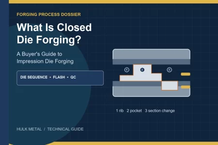
These articles help buyers connect the coupling-hub drawing to forging process, tolerance release, material grades, quality-system evidence and forged-versus-cast failure analysis. They are supporting technical reading for the drawing review, material and inspection decisions described on this page. Read them alongside the finished-part drawing, forging reference and approved specifications so process decisions remain tied to the actual coupling interface and order. The purchase drawing, approved specifications and quotation revision remain the controlling documents.