


Forged and cast mining parts carry different process signatures, but one photo cannot prove the cause. Start with location, duty, repeatability and records. Then match the suspected condition to the inspection method and acceptance rule.

Field clues, inspection limits and records to preserve before replacement.
Forged vs Cast Mining Spare Parts: Failure Modes You Can Spot
-
Home>
-
Blog>
-
Technology>
Forged vs Cast Mining Spare Parts: Failure Modes You Can Spot
10
2026.11
Mining spare-part failure dossier
The fracture is evidence. The supplier label is not.
Use location, repeatability, surface condition and test method to decide what the failed part is telling you; then build a replacement enquiry that can be verified.
A forged mining spare part and a cast mining spare part can fail in the same machine, the same shift and at the same load path. The useful question is not which process sounds stronger. It is where the damage began, what pattern surrounds it and which test can prove the suspected condition.
Forging deforms a solid heated billet. Casting fills a cavity with liquid metal and then solidifies it. That difference changes the likely defect family, but it does not make every forging sound or every casting weak. Machining, heat treatment, fit, wear, impact and maintenance can hide or create the evidence.
This guide is written for a failed or suspect mining component before the purchase order for its replacement. It follows the evidence in the order an inspector can actually collect it: service location, process signature, surface feature, crack or wear path, inspection scope and acceptance record.
Start at the Failure Location, Not the Manufacturing Label
The first reliable entry point is the failed part in its assembly, before someone cleans, grinds or sectioning the evidence away.
Mark the installed orientation and photograph the complete assembly before removal. Then photograph the loose part from both sides, both ends and a scale reference. A close-up without orientation can make a flash-line crack look like a random surface mark, or make damage from a mating component look like a material defect.
Select the evidence category that is missing; the full notes remain visible below.
No evidence category selected.
A defect that appears at the same die radius on every rejected part is not equivalent to a random gouge found on one returned item. One points toward die design, fill or handling before release; the other may have occurred after installation. The conclusion depends on repeatability across a batch and on where the mark sits relative to the working surface.
Time is also evidence. A crack found before the part enters service has a different investigation path from one that appears after a repair, a changed load or an extended maintenance interval. Ask for the installation date, operating hours, repair history and replacement interval. Those records may explain more than a material certificate taken in isolation.
Field rule: record the evidence first, then name the failure. Cleaning, machining or destructive sectioning can remove the location that would have shown whether metal folded, two flow fronts met, a crack followed a trimmed edge or a mating part initiated wear.
How Forged and Cast Mining Parts Leave Different Process Signatures
Forging and casting begin from different material states, so their characteristic manufacturing defects are not interchangeable.
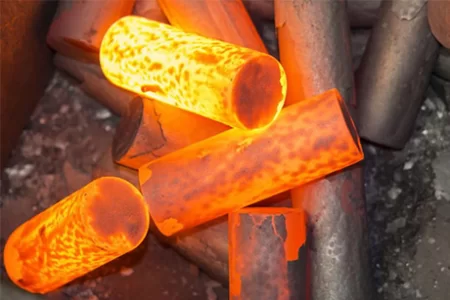
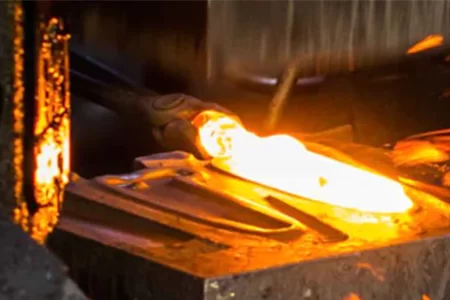
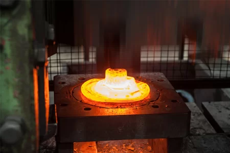
A hot die forging starts with a solid billet. The billet is heated, positioned in the die and deformed. Metal flow follows the die cavity and often produces a flash line that is later trimmed. The process can leave underfill, laps or folds, cold shuts, mismatch and flash-line cracks. The forged structure also develops a directional flow pattern that may be exposed by sectioning or macroetching.
A casting starts with liquid metal that fills a mould and solidifies. Its characteristic concerns include shrinkage and gas porosity, hot tears, mould-related surface conditions and segregation. A machined bore or pocket may cut into a void that was not visible on the outside. A rounded internal surface may be a clue, but it cannot establish porosity without an appropriate examination.
Forged process clues
What the inspector looks for: a trimmed flash line, directional flow, missing metal at a hard-to-fill feature, a surface fold, a cold-shut seam or die mismatch. A repeat at the same tooling location is more informative than a single mark.
What evidence can test it: die and drawing comparison, macroetch or sectioning where specified, visual examination and agreed surface or internal NDT.
Cast process clues
What the inspector looks for: mould skin, abrupt changes in surface condition, exposed rounded voids, shrinkage indications or thermal tears. The outer skin can conceal internal solidification defects.
What evidence can test it: controlled sectioning, radiography or ultrasonic examination when specified, and a review of the casting and acceptance drawings. A visual guess is not a porosity determination.
Table 1. Compare the evidence questions, not a slogan about which process is better.
| Evidence question | Common forged-part channel | Common cast-part channel | Why the label is not enough |
|---|---|---|---|
| Missing geometry | Underfill or unfilled die corner | Mould fill, shrinkage or core-related condition | Both can leave missing or displaced material |
| Surface opening | Lap, cold shut or flash-line crack | Hot tear, inclusion or mould-related discontinuity | Surface cleaning may remove the clue |
| Internal soundness | Internal forging defect or inclusion | Shrinkage or gas porosity | Requires internal rather than surface-only inspection |
| Geometry shift | Die mismatch or wear | Mould/core movement or distortion | Machining can hide the original cause |
| Heat-related failure | Post-forge treatment or cracking at section change | Solidification or post-cast treatment path | Final thermal condition belongs to the whole route |
Grain flow deserves careful language. Deformation can produce a directional flow pattern in a forging, while a casting solidifies without that same flow story. That difference is useful in a controlled metallurgical examination. It does not prove that every forged part is tougher, that a cast part has no directional structure, or that a single polished face is sufficient to determine the cause.
The correct question is therefore narrower: which defect family is consistent with the drawing, process route and failure location, and what test can confirm it without destroying the useful evidence?
Read Surface Features Before Calling Them Defects
A visual feature is a lead, not a verdict. Its position, edges, repeatability and relation to the working surface determine which manufacturing or service mechanism deserves investigation.
Surface inspection is most useful before cosmetic cleaning. Rust, mud, paint and handling damage all compete with the original mark. Clean only the minimum area needed to see the feature, and preserve photographs and a note describing what was removed. A maintenance team that sends only a polished close-up has already removed part of the evidence trail.
Missing metal at a thin rib or tight corner
Symptom: the contour is incomplete at a feature that was difficult to fill, often with a rounded or short edge. Forging question: was the billet volume, blocker sequence, die condition or transfer time unable to fill that end of the impression? Cast question: did the mould or core fail to fill or hold its position? Compare the location across the batch and against the released geometry before assigning a cause.
A folded seam near a step, radius or parting line
Symptom: a line that resembles a flap or an oxide-filled fold rather than an open fracture. Likely direction: review metal flow, billet placement and die radii in a forging. Do not confuse it with: a crack, a machining mark or a repair blend. Inspect the line before and after agreed cleaning, then follow the required sectioning or NDT method.
A seam where two metal fronts appear to meet
Symptom: a linear discontinuity at a symmetric web, deep rib or last-to-fill location. Forging question: did separate metal streams meet after one surface cooled? Cast question: is the location associated with a mould/core boundary or thermal contraction? Map it on the drawing and compare several parts before assigning the process origin.
Rounded pits after scale removal
Symptom: dark or shallow depressions that remain after blasting or machining stock removal. Forging question: was heated scale rolled into the surface or trapped in the die? Alternative: corrosion pitting or handling damage after delivery. Compare the untouched surface, cleaned surface and machining allowance; depth relative to the finished face matters more than colour.
A step on one side of the die line
Symptom: the two sides of a formed part do not line up, or the wall thickness changes in one direction. Process direction: die alignment, insert fit or billet position may move the parting line. Measure near the parting line as well as at the finished datums. A mismatch direction repeated across the lot supports a tooling or setup review.
Rounded voids exposed by machining
Symptom: cavities appear only after a bore, pocket or seal face is cut. Possible direction: internal solidification porosity in a casting, a forging-related internal condition or another inclusion path. Preserve the cut surface and removed material, locate the void relative to the original skin and obtain the specified internal inspection or sectioning method.
Table 2. Convert a visible clue into the next evidence question.
| Visible clue | First engineering question | Evidence to preserve | Unsafe shortcut |
|---|---|---|---|
| Short fill at a corner | Does the miss repeat at the same die or mould feature? | Batch location map, drawing view and process route | Calling every short fill a material problem |
| Folded line | Does the line follow a radius, step or flow path? | Uncleaned photographs and a position sketch | Grinding it away before recording depth |
| Open crack | Is it surface-open, and along which feature does it run? | Orientation, length, branching and mating parts | Using UT or PT without matching the location to method scope |
| Rounded void after machining | Was the defect at the original skin or inside the section? | Cut-up location, removed chip/material and process records | Declaring casting porosity from shape alone |
| Repeated step | Is the mismatch direction the same across the lot? | Measurements on both sides of the formed feature | Measuring only the final machined face |
Separate appearance from mechanism. A dark line may be a lap, a crack, a tool mark or foreign material. A rounded hole may be gas porosity, shrinkage, an inclusion pulled out in service or mechanical damage. The drawing and an appropriate inspection method decide what evidence is strong enough.
Locate Cracks, Fractures and Wear Before Choosing NDT
The method follows the suspected location. Surface-open flaws, near-surface flaws and internal flaws require different inspection logic.
Penetrant testing (PT) is intended for discontinuities open to the surface. The locally archived ASTM E165 scope lists cracks, seams, laps, cold shuts, shrinkage, laminations, through leaks and lack of fusion. If a suspected void is closed below the skin, PT is not the method that can open the section for you.
Method-selection gate: first mark the suspected defect depth, then choose the inspection family. Do not select PT, MT or UT from a generic checklist before locating the evidence on the part.
Magnetic particle testing (MT) is used for surface and near-surface discontinuities in ferromagnetic material. The locally archived ASTM E1444 scope includes cracks, laps, seams and inclusions. Material condition and surface preparation matter. A non-ferromagnetic part changes the applicable method, and a drawing requirement must be followed.
Ultrasonic testing (UT), as reflected in the locally archived ASTM A388 scope, is used to detect internal flaws. The result depends on access, geometry, surface condition and the written technique. A UT indication is not the same as a PT indication, and neither result supplies the purchaser's acceptance level by itself.
Table 3. Match the suspected location to the inspection method and required record.
| Suspected condition | Method family to discuss | What the method can address | What must still be defined |
|---|---|---|---|
| Surface-open crack, lap or cold shut | PT where specified | Discontinuities open to the inspected surface | Surface preparation, zone, stage and acceptance |
| Surface or near-surface indication in ferromagnetic steel | MT where specified | Cracks, laps, seams and inclusions on or near the surface | Material condition, magnetisation method, zone and acceptance |
| Suspected internal flaw | UT where specified | Internal flaws within the inspected volume | Geometry, access, technique, coverage and acceptance |
| Macro-structure concern | Macroetch or sectioning where specified | Macro conditions compared with an agreed rating method | Sampling location, reference chart and evaluation rule |
| Inclusion concern | Specified chemical or metallurgical examination | Evidence relevant to the declared method | Sampling plan and the purchaser's acceptance basis |
Follow the crack before naming it
A crack along a trimmed flash line raises questions about trimming, edge condition, temperature and material sensitivity. A crack that starts at a bolt hole, radius or mating-part contact raises questions about fit, stress concentration and assembly. A crack that begins at a repaired or welded area raises a separate route question. Those are not the same failure just because the final break looks similar.
Map first: draw the crack origin, path and termination on an oriented part view. If the path crosses a trimmed edge, a machined feature and a service-contact area, each segment needs its own explanation.
If the part is already separated, keep both fracture faces. Do not repeatedly open and close the break, and do not grind the origin while looking for a stamp or part number. Wrap the faces, identify the orientation and photograph the progressive markings before any destructive examination. A fracture-surface specialist may later use those details; the replacement quotation cannot reconstruct them.
Distinguish wear from overload
Abrasive wear removes material gradually and usually leaves a directional pattern related to the material flow over the surface. Overload can bend, spread, crack or deform the part in the direction of the applied force. The distinction affects the replacement question: a harder surface may not correct a load, fit or assembly problem, and a stronger section may not solve abrasive loss.
Record the worn area relative to the original drawing, the contact surface and the replacement interval. If several parts wear in the same place, the geometry, material condition, abrasive environment and maintenance practice become part of the investigation. If one part deforms while neighboring parts do not, confirm the load event, mating alignment and possible removal damage before changing the specification.
Separate Method Evidence From Acceptance Authority
An inspection standard can describe a method and still leave the rejection decision to the purchaser.
The local technical record notes that ASTM A275 and A388 do not contain the purchaser's acceptance levels. The purchase order or drawing has to identify the applicable requirement, inspected zone, stage and disposition rule. This is not a paperwork detail. It determines whether an indication is recordable, repairable, subject to concession or a reject.
Myth: a “passed NDT” stamp is enough
Without the method, coverage, stage and acceptance reference, the stamp does not tell the buyer what was inspected or why the result was accepted.
Fact: the record must connect method to requirement
The useful record names the part and drawing revision, inspection stage, method, coverage, result and the controlled acceptance document used for disposition.
A practical disposition path has four gates. First, contain the suspect parts and preserve their identity. Second, confirm the drawing revision, material condition and inspection stage. Third, repeat or extend the specified examination where the method is valid. Fourth, record one decision: accept, hold for engineering, rework under an approved route, concession or reject.
Do not convert a missing acceptance criterion into a supplier judgement after delivery. If the drawing does not say what counts as acceptable, request the missing decision before replacing the lot. The same rule applies to a failure investigation: an observed indication may justify a hold, but it does not by itself prove root cause.
Build a Failure Dossier the Supplier Can Actually Use
A replacement enquiry becomes useful when it separates service damage from manufacturing evidence and gives the supplier enough context to quote the right part and inspection route.
Photographs are not a dossier by themselves. The supplier needs to know which image shows the installed orientation, which side is the working face, where the part sat in the assembly and whether the damage appeared before or after a repair. Put the photographs in context and keep their original files.
Use this checklist to test whether the evidence pack is complete before sending an RFQ.
The failed part can also help the supplier identify a missing datum, an ambiguous corner radius, a wear allowance or an assembly clearance that was not clear from the original drawing. Mark those questions on a red-lined copy rather than sending a new sketch without revision control. The replacement should follow an approved definition, not a set of separate email assumptions.
On our production floor, we review the drawing before the process route because the forged shape and finished-part requirements are not interchangeable. A reviewer has to know which surfaces remain as-forged, which features receive machining allowance and which dimensions will be checked after outsourced heat treatment.
Factory review point: the failed part may explain the service problem, but the replacement still needs a controlled drawing, material condition, heat-treatment requirement and acceptance method.
When the buyer supplies a failed part, we ask for its orientation and the working face before discussing a redesign. The broken part can explain the service problem, but it cannot replace the released material grade, dimensional limits, heat-treatment requirement or acceptance rule. Missing commercial values such as MOQ and lead time are confirmed for the actual drawing and order.
What to send for a replacement quote
01
Part identity: name, machine assembly, drawing number, revision and the position of the failed item. Include the year or batch if known.
02
Duty description: what the part carries, pushes, guides or wears against; whether the load reverses; whether impact and abrasive material are present.
03
Failure evidence: oriented photographs, origin mark, crack or wear path, deformation, mating-part condition and the time or event at which the problem appeared.
04
Acceptance requirement: dimensions, material verification, hardness, mechanical testing and NDT method or inspection zones required by the drawing or purchase order.
05
Route and order: finished condition, outsourced heat treatment, machining, surface protection, marking, packing, quantity and delivery pattern.
This structure produces a more useful quotation than the phrase “quote the same part.” It tells the supplier where the evidence is incomplete, which operations belong in the delivered scope and which technical values remain unresolved.
When Forging Fits and When Casting May Be the Better Question
The correct process recommendation follows the duty, geometry, material, production route and acceptance method. It is not a loyalty test between two process names.
Hot die forging is often relevant when a custom solid part needs controlled deformation and a directional structure that can be examined against the drawing. It can suit brackets, links, clevis-type connecting hardware, mounting hardware, wear parts and other OEM mining components within the confirmed scope. The die, billet, heating and trimming route must still match the geometry.
Comparison rule: compare the achievable geometry, material, inspection coverage and delivered condition. A process name alone cannot establish which part is safer in service.
Casting may be the better engineering question when the shape needs a complex internal cavity, a hollow form or a geometry that would be difficult to eject from a forging die. A sound casting with an appropriate material, solidification control and acceptance plan can serve a mining application. Replacing it with a forging only because the word sounds stronger can create a different set of fill, draft, trimming and machining problems.
Table 4. Use the duty and evidence path to choose the next engineering question.
| Buyer condition | Useful next question | Evidence to define | Stop condition |
|---|---|---|---|
| Solid load-bearing or wear part within forgeable geometry | Can the drawing be converted into a repeatable hot die forging route? | Forging drawing, practical radii, machining allowance, heat treatment and inspection | Geometry or requested material is outside the confirmed scope |
| Complex hollow or cavity-led shape | Does the casting route actually control the internal soundness and critical zones? | Casting drawing, material, solidification route, sectioning or internal inspection | The proposed method cannot inspect the failure-critical section |
| Repeated crack at the same assembly point | Is the cause fit, load, surface condition or the supplied part? | Mating-part condition, installation record, fracture origin and assembly measurements | A process comparison is attempted before the load path is understood |
| Abrasive wear across many parts | Does the replacement need a geometry, material or maintenance change rather than a process-name change? | Wear direction, contact area, operating environment and replacement history | The proposed material cannot be tied to the observed wear mechanism |
Decision rule: choose the process that can form the part and provide evidence at the critical location. If neither route can be verified against the duty and acceptance requirement, the correct next step is an engineering review, not a supplier comparison based on one adjective.
HULK Metal supplies OEM custom hot die forged parts to the buyer's drawing. The confirmed public route includes induction heating, multiple forging presses, in-house inspection and heat treatment through an audited partner under ISO 9001. It does not maintain a stock catalogue, publish equipment tonnage or offer generic tolerance, hardness, weight, MOQ or lead-time values.
Gears, shafts, aluminium forging, cold forging, ring rolling, forged wheels, titanium forging, H13 or D2 tool-steel forgings and grade 4340 are outside the confirmed scope. Automotive, chemical including refining and petrochemical, medical and high-precision industry applications are also out of scope. Open-die forging is not presented as a confirmed production route.
Mining Spare Part Failure Questions Buyers Ask
These short answers separate what a buyer can observe in the field from what needs a defined inspection or engineering review.
Can I identify forged versus cast from a photograph?
A flash line, trimmed edge or directional flow clue can support a hypothesis. A photograph alone cannot certify the process. Machining, coating, repair and service damage can hide the original surface. Use the drawing and production record before treating the label as proved.
Is a lap always a forging defect?
Not always. A line must be separated from a crack, tool mark, repair blend or service gouge.
Should every returned mining part receive PT, MT and UT?
No. PT addresses surface-open discontinuities, MT addresses surface and near-surface indications in ferromagnetic material, and UT addresses internal flaws. Method, coverage, inspection stage and acceptance should follow the risk location, drawing and purchase order. Applying every method without a defined disposition rule creates records that cannot be compared across lots.
What if the casting or forging supplier says the part “passed inspection”?
Ask for the part, drawing revision, method, coverage, result and acceptance reference.
The strongest replacement enquiry does not ask the supplier to defend a process name. It supplies the failed part's story, the drawing and the acceptance requirement, then asks which route can satisfy those conditions and what evidence will prove it.
Article Navigation
Others You Might Want to Know
Article Navigation
Industries
Foundries
More Mining Part Failure and Forging Inspection Articles


Previous article: None
Next article: What Truly Affects Custom Forged Parts Cost?