Define the mating part, datum scheme, flange face and bolt pattern before comparing suppliers. Those inputs decide whether the drawing is ready for a useful forging review.
Keep the Process Boundary Visible
HULK Metal offers OEM hot die forging. A drawing that requires continuous ring-rolled geometry belongs with a ring-rolling supplier, not this route.
Build One Acceptance Family
Read face flatness, bolt-hole position, bore alignment and runout against the same datum chain. Individual dimensions can pass while the assembled interface still fails.
Release Material and Inspection Together
Material grade, heat-treatment condition, hardness location, NDT method and acceptance must be stated before quotation. Missing values stay per drawing or Contact us for details.
Control the Whole Supply Chain
Forging, machining, outsourced heat treatment, inspection, marking and packaging are coordinated through one responsible contact, with records checked before dispatch.
WIND-TURBINE FLANGE AND HUB PARAMETERS REVIEWED AT DRAWING RELEASE
The parameter sheet is an RFQ control list, not a stock-size table. It shows which decisions must be traceable before HULK Metal can review an OEM forging route; dimensions, tolerances, weights, inspection levels and commercial terms remain tied to the buyer's drawing and purchase order.
Parameter
Release Information
HULK Metal Rule
Part family
Tower, nacelle, hub or adapter interface
Reviewed as an OEM part to drawing
Process route
Hot die forged blank and machining scope
Ring rolling is not offered
Material
Grade, condition and material certificate request
Material grade per drawing
Heat treatment
Route, hardness band and sampling location
Carried out by an audited partner
Machined geometry
Face, bore, bolt pattern, datum and runout
Acceptance criteria per drawing
NDT
Method, coverage, stage and acceptance
Named in the drawing or purchase order
Commercial scope
Quantity, delivery split, marking and packing
Large-diameter flange MOQ confirmed per drawing
Quality system
Inspection and batch-record requirements
ISO 9001 only
Wind Turbine Flanges and Hubs Made to Your Drawing
Interface Integrity Dossier
HULK Metal reviews OEM wind-turbine flange and hub work as a drawing-led hot-die-forging project. The useful starting point is not a catalogue size but the mating interface, material condition, machining allowance, inspection requirement and order quantity. Buyers can use the sections below to separate interface decisions from supplier claims, identify the point where ring rolling sits outside the offered route, and prepare a drawing package that can be quoted and inspected.
The page is written for a buyer who has a drawing but may not yet have separated tower, nacelle, hub or adapter geometry. It shows which details must be settled before a supplier can quote, forge, machine and inspect the part without inventing assumptions.
A second boundary matters from the start: HULK Metal offers hot die forging for approved OEM part classes, not ring rolling. If the design requires continuous ring-rolled geometry, the correct next action is to source a ring-rolling supplier rather than force the part through an unsuitable route.
Drawing release rule: If the flange name, mating component, datum scheme or inspection basis changes between documents, stop the RFQ and correct the source drawing first. A quotation is only as reliable as the revision it references.
Start With the Mating Interface, Not the Part Name
A wind flange is not one universal geometry. The same term may cover a tower-section joint, a tower-to-nacelle connection, a hub-side adapter or another interface named by the turbine designer. The interface controls the questions that matter: which face carries the load, which datum establishes the bolt circle, which bore or pilot centres the joint and which dimensions must stay readable after machining.
Use the interface selector to follow the three common naming groups. All panels remain visible when JavaScript is unavailable.
Tower interface: define the section joint and access condition
The tower-side drawing should identify the mating section, flange thickness, bolt-hole pattern, face condition, internal or external access and whether the part is supplied as-forged or finish-machined. The buyer also needs to say how the flange will be handled after coating, because the mating face and bolt-hole entries may need protection.
Ask for one datum scheme that survives from machining through inspection. If the fabrication drawing, machining drawing and inspection sheet use different centres, the supplier must create assumptions that the buyer did not authorize.
Nacelle interface: separate the bearing, bedplate and adapter references
A nacelle-side part may connect through a yaw bearing, a bedplate interface, a geared drivetrain housing or a direct-drive adapter. The name on the purchase order is not enough. State the mating component, the interface that controls centring, the bolt circle and the face that must remain square to the assembly axis.
When several drawings are supplied, list the controlling revision for each feature. This prevents a supplier from quoting an older forging outline while machining to a newer interface drawing.
Hub or adapter: clarify the geometry before using the word hub
Hub can describe a rotor-side body, a hub adapter, a bearing interface or a power-transmission hub in another industry. For this page it means a wind-energy OEM part reviewed to the buyer's drawing. The drawing must show whether the scope is a forged blank, a machined component or a sub-assembly interface.
HULK Metal does not infer the surrounding rotor design. The buyer remains responsible for the system interface; the supplier review covers manufacturability, process route and the agreed acceptance evidence.
Drawing item
Question to settle
Why it changes the quote
Mating component
What part seats against this flange?
Defines the controlled face and assembly direction
Primary datum
Which centre and face locate every feature?
Prevents separate machining and inspection assumptions
Bolt circle
How are pitch, angular position and hole size controlled?
Determines machining and gauge strategy
Surface condition
Is the face as-machined, coated or protected?
Changes handling, finish and final inspection
If the interface cannot be named, the drawing is not ready for a comparable quotation. Send the mating-part geometry and the controlling revision together; HULK Metal can then separate what must be forged, what must be machined and what remains the buyer's design responsibility.
Wind Flange, Tower Flange or Hub Part: Name the Geometry First
The word flange describes a function, not a complete manufacturing plan. A tower flange usually controls a bolted section joint; a nacelle-side flange may centre a bearing or housing; a hub or adapter part may combine a large body with one or more machined interfaces. Calling every item a wind flange hides these differences and produces vague quotations.
Start with the geometry and scope. Then confirm the process boundary. A hot-die-forged blank with machining stock is not interchangeable with a continuously ring-rolled flange, and neither route should be written as if the other does not exist.
Part naming
Typical control point
HULK Metal route
Stop condition
Wind-turbine flange
Mating face and tower or machine joint
OEM hot die forging plus drawing-defined machining
Drawing mandates ring rolling
Tower flange
Section alignment and bolt pattern
Reviewed per drawing and order plan
Interface drawings conflict
Hub body or hub adapter
Centring bore, flange face and assembly datum
Reviewed as an OEM forged component
System design is left for the supplier to invent
Generic forged flange
Face, bore and bolt pattern
Allowed only when the wind interface is also defined
Term is used without mating-part context
Process boundary: HULK Metal does not provide ring rolling or rolled-ring forging. If the buyer's manufacturing specification requires a continuously rolled ring, the drawing should go to a supplier whose approved process is ring rolling.
A short part-family statement in the RFQ removes much of the ambiguity: “tower-section flange, hot-die-forged blank, finish-machined face and bolt pattern, NDT to drawing.” That sentence gives the supplier a geometry, process and acceptance path. A title alone does not.
Why Diameter Changes the Forging and Machining Plan
Large diameter affects more than the amount of material in the part. It changes how the blank is handled, how the die and press route are planned, how the part is located for machining, how the face is measured and how the finished part is protected before shipment. Those effects belong in the order review even when the drawing does not state a size range.
The points below are decision gates, not published equipment limits. Feasibility, maximum size and commercial scope are confirmed for the drawing through Contact us for details.
1
Billet and heating plan
Material section, heated volume and handling method must suit the forged shape. A larger plan affects how the billet reaches the die and how the heating window is controlled.
2
Forging and allowance
The as-forged outline must leave enough controlled material for the face, bore and bolt pattern. Extra stock is not free; it adds machining time and can change the datum strategy.
3
Machining setup
The machinist needs a stable locating scheme that relates the forged body to the final mating face. The same scheme must remain usable for CMM inspection and rework analysis.
4
Inspection and packing
Large faces and multi-hole patterns need a planned measurement path. The finished part also needs protection that keeps the controlled face and bolt-hole entries in their accepted condition.
This is why “large-diameter flange, quantity later” is a weak RFQ. The quantity and geometry decide whether a reviewable route exists, how much handling risk the order carries and which inspection stage should be planned. MOQ for large-diameter flanges is confirmed per drawing, not quoted from a stock rule.
Material and Heat-Treatment Conditions Belong in the Drawing
Material selection is a buyer design decision. HULK Metal can review carbon-steel and alloy-steel OEM parts, but the exact grade, condition and verification requirement must come from the drawing or the approved specification. A grade name without condition is incomplete; a hardness value without test location and method is not a controlled acceptance requirement.
Specification rule: A material designation and a delivered condition are separate requirements. Both need to be visible before the RFQ can be reviewed against a heat-treatment and inspection plan.
HULK Metal routes the required heat treatment through an audited external partner. That route must appear as part of the manufacturing record, not as an in-house claim. The buyer should state the required process family, hardness band, sampling position and documentation because those requirements determine how the part is tested and released.
Drawing field
What HULK Metal expects
Why it matters
Material grade
Grade and applicable material specification
Controls billet verification and process planning
Delivery condition
As-forged, normalized, quenched and tempered, or other drawing-defined state
Changes the heat-treatment route and machining condition
Hardness
Range, test method and sampling location
A number without a location cannot be accepted consistently
Mechanical testing
Test type, frequency and specimen direction where required
Defines the batch evidence package
NDT
Method, coverage, stage and acceptance level
Prevents a general “inspection” line from replacing the contract
Traceability
Heat number, batch, marking and document set
Connects the delivered part to material and process records
Material first
The supplier cannot choose a convenient substitute when the drawing names a grade. If an equivalent is proposed, it needs buyer approval and traceable qualification.
Condition second
The same grade can require different heat-treatment and testing plans. State the final condition as well as the steel designation.
Evidence third
Name the required certificate, mechanical results, hardness record and NDT report. Do not leave “quality documents” undefined.
When the drawing does not contain a value, keep the missing item visible in the RFQ. Do not invent a tolerance, hardness band, sampling frequency or acceptance level to make the quotation look complete.
Bolt Pattern, Face Flatness and Runout Are One Acceptance Family
A flange can pass individual dimensions and still fail assembly. The bolt pattern may fit the gauge while sitting off the intended angular position; the face may measure locally flat while being out of square to the bore; the bore may sit within diameter while its centre moves relative to the bolt circle. These errors interact through the datum chain.
Read the acceptance family together: face, bore, pitch circle, bolt-hole position and runout relative to the stated datums. The diagram uses a generic geometry only; the actual features and their limits come from the buyer's drawing.
Controlled face: Define the seating face and the condition that must survive machining, coating and handling. A visually clean face is not an accepted interface.
Centring feature: Identify the bore, pilot or other feature that centres the joint. Confirm its relation to the assembly axis and the primary datum.
Acceptance-family rule: Face and centring features are useful only when the inspection report relates them to the same datum used for machining and assembly.
Bolt pattern: State hole size, pitch circle, angular spacing, position tolerance and any requirement for hole-to-hole or clocked alignment.
Runout and squareness: Specify which surface is measured against which datum. “Runout” without a reference is not a release criterion.
Inspection principle: Use one datum scheme for machining, CMM programming and final report. If the inspection report uses a different centre from the machining setup, the numbers may be precise but not comparable.
For high-load bolted joints, preload and face condition affect how the joint behaves under fluctuating load. That is an engineering reason to treat the interface as a system rather than a collection of independent dimensions. The design assumptions remain with the buyer's engineering team; the supplier's role is to manufacture and verify the released requirements.
Failure Modes That a Clean Flange Surface Can Hide
Visual inspection is useful, but it cannot prove that a flange is ready to assemble. A clean surface may still hide laps, seams, local grinding damage, a displaced hole pattern or a datum inconsistency. The table below turns each risk into an acceptance question that belongs in the drawing or purchase order.
Evidence gap
What can look acceptable
What can fail later
Acceptance control
Surface laps or seams
Coated or blasted exterior
Crack initiation under cyclic service
Drawing-named visual and NDT acceptance
Datum disagreement
Each report passes its own check
Bolt pattern or bore is offset in assembly
One released datum scheme across documents
Face damage after machining
Final inspection passed before packing
Poor seating after transport or handling
Protected face, packing check and dispatch record
Heat-treatment mismatch
The specified grade is printed on the drawing
Wrong hardness or mechanical condition
Route, furnace-partner record and sampling evidence
Undefined NDT
“Inspection” is named generically
Method, coverage or acceptance is disputed later
Method, stage and acceptance level in the order
Why a dimensional report can be right and the joint still wrong
If the machinist and inspector use the same nominal dimensions but different datums, both reports can look internally consistent while describing different physical relationships. The interface question has two parts: is the hole at X, and is X measured from the same controlled centre and face used by the assembly? A report that answers only the first part leaves the assembly risk unresolved.
Why surface appearance cannot replace NDT
Grinding, shot blasting or coating can remove visual evidence without changing the internal condition. The drawing must name the NDT method and acceptance.
Why heat-treatment records belong to the order file
The forging supplier and heat-treatment partner are separate process locations. A controlled order links the material batch, heat-treatment route, hardness or tensile result and finished identification so a later question can be answered from evidence, not recollection.
Before accepting a replacement supplier, ask which evidence changes when the drawing changes. A supplier that treats face, bolt pattern, material state and NDT as independent line items is less likely to catch an interface conflict before production.
Build a Drawing-First RFQ That Produces a Usable Quote
The RFQ should let the supplier review the part without guessing the interface or the acceptance boundary. Start with the drawing and finish with the commercial release. The checklist below is a conversation aid, not an online approval system: each unchecked item remains a buyer action.
0 of 8 RFQ controls reviewed
What HULK Metal needs before the process route can be reviewed
1
Send the drawing set
Include the forging drawing, finished-part drawing and every revision that controls the interface. Mark which document controls each face, bore, hole and note.
2
State the process boundary
Confirm whether the buyer is asking for a hot-die-forged blank, a finish-machined flange or a combination. A ring-rolling requirement is outside this route.
3
Name the acceptance package
List material records, dimensional report, hardness and tensile checks, NDT method and any marking or traceability requirement.
4
Release quantity and packing
State batch quantity, delivery split, destination, protection for machined faces and the document set required at dispatch.
Useful RFQ line: “OEM wind-turbine flange, hot-die-forged blank, final face and bolt pattern machined to the controlling drawing, material and heat treatment per drawing, dimensional report plus the drawing-named NDT method, quantity and packing to be confirmed.” It is clearer than a list of keywords because it tells the supplier what must be reviewed.
Large-diameter flange MOQ is confirmed per drawing. That wording protects both sides from pretending that quantity is independent of geometry, material, inspection and transport. If the project has staged deliveries, send the split with the first RFQ rather than waiting for a commercial negotiation.
What We Look For Before a Wind-Flange Drawing Is Released
In our workshop, the useful review happens before the first billet is cut. We compare the customer drawing with the mating interface and the inspection plan, because a dimension that cannot be measured from the released datum is not a production instruction. A clean-looking purchase order can still hide a weak release.
We check the revision trail
If the forging outline, machining drawing and inspection sheet do not carry the same interface revision, we stop and ask which document controls the order.
We check the machining stock
The forged shape must leave material where the face, bore and bolt pattern need to be generated, without turning the machining allowance into an unplanned recovery operation.
We check the evidence route
A drawing that names an NDT acceptance but not the method or stage cannot produce a comparable release record. We resolve that before promising a quotation.
We also check the commercial assumptions that sit behind the drawing. Large-diameter parts may require a tooling, handling or inspection plan that a stock-part RFQ would never reveal. Those points are confirmed per drawing, not hidden behind a generic “custom parts” claim.
If the result of the review is that the drawing sits outside the hot-die-forging route, we say so. That includes a ring-rolling requirement. A clear stop is more useful than accepting a drawing that cannot be manufactured under the offered process.
Questions Buyers Ask Before Releasing a Drawing
These questions usually appear after the product category is clear but before the purchase order is released. The answers stay within the approved OEM hot-forging scope.
Can HULK Metal supply a wind flange with machining?
Yes, OEM flange and hub work can be reviewed as a hot-die-forging route with drawing-defined machining. The quote must state which faces, bores, holes and inspection features are included; machining beyond the released drawing is not assumed.
Is ring rolling available?
No. HULK Metal does not offer ring rolling. Use a ring-rolling supplier when the approved design requires it.
Can you quote a MOQ for a large flange?
MOQ for large-diameter flanges is confirmed per drawing. Geometry, material, inspection and handling can change the order plan, so a fixed catalogue MOQ would be misleading.
Can heat treatment be included?
The required thermal processing is completed by an audited external partner. The route, hardness band, sampling location and records must be stated in the drawing or purchase order so the external process can be verified against the order.
Can NDT be added to the scope?
NDT can be included when the buyer names the method, coverage, stage and acceptance level. The drawing or purchase order must define the requirement; HULK Metal does not choose an acceptance level on the buyer's behalf.
Do you hold certifications beyond ISO 9001?
No additional certification claim is made here. ISO 9001 is the quality-system reference used on this page. Certificate numbers, issuing bodies, validity dates, scope statements and other schemes are not stated unless separately supplied and verified.
Quality Control: What We Test and How
Quality control starts with the released drawing and ends with a traceable dispatch package. The inspection route is selected for the part, material condition, machining stage and buyer-specified NDT. Measurements and records are kept with the batch, while any missing acceptance criterion returns to the drawing review rather than becoming an informal shop-floor rule.
1
Raw Material Inspection
Material grade and identification are checked against the order. Chemical composition and material records are reviewed before release to production, with the heat number kept traceable to the batch and the final inspection package.
2
Production Inspection
Billet preparation, heating and forging are checked against the work instruction. The operator and inspector look for laps, seams, underfill and handling damage before the part moves to the next stage.
3
Dimension Inspection
Machined faces, bore, bolt pattern and runout are measured against the released datum. CMM or other drawing-defined methods are selected so the report uses the same feature references as the machining plan.
4
Load and Mechanical Verification
Hardness and tensile checks are completed where the drawing specifies them. Test method, location and frequency follow the order; no universal value is substituted for the buyer's engineering requirement or its stated acceptance condition.
5
Surface and NDT Inspection
Visual surface condition is checked against the drawing. When UT, MT or PT is required, the named method, coverage, timing and acceptance level are recorded by the responsible inspection stage.
6
Finished Product Inspection
The finished part is checked for marking, drawing revision, machined condition, protected interfaces and the required document set. Nonconforming items are separated before packing, with the disposition recorded against the batch and the buyer's release requirement.
7
Packaging Inspection
Contact faces, bolt-hole entries and exposed edges are protected as agreed. Quantity, labels, packing list and shipping documents are checked before the batch leaves the works, so the identification used in inspection remains readable after transport.
Next action: send the interface definition with the product name
For a useful wind-flange or hub quotation, send the controlling drawing, the mating component, the material and heat-treatment condition, the required NDT, the batch quantity and the packing requirement. HULK Metal will confirm the hot-die-forging route per drawing and identify any item that belongs with another process.
Representative process imagery on this page shows OEM hot-forging work and inspection capability. It does not depict a specific customer component or release a final geometry; the buyer's drawing controls material, dimensions, tolerances, machining and inspection.
FORGING, MACHINING AND INSPECTION ROUTE FOR WIND-FLANGE WORK
OEM flange and hub work passes through connected decisions rather than isolated departments. Material release, hot-die forging, outsourced heat treatment, machining and batch inspection are planned together so the drawing, process route and shipping record refer to the same revision.
Production Workshops
Manufacturing Equipment
Inspection Center
Warehouse
Packaging
Surface Treatment Center
Production Workshops
The production route begins with drawing release and material verification, then moves through billet preparation, induction heating and hot die forging. Work instructions stay tied to the released drawing so the as-forged geometry leaves the intended machining allowance and datum material. Any process change that could affect the mating face, bolt pattern, heat-treatment response or inspection stage is reviewed before the next batch begins.
Manufacturing Equipment
Induction heating and multiple forging presses support the hot-forging route. CNC machining follows to produce the flange face, bore, bolt holes and other drawing-defined features. Equipment selection is made from the part geometry and order plan rather than a published size catalogue. Equipment tonnage, maximum part size and cycle details are confirmed for the drawing through Contact us for details.
Inspection Center
Incoming material, in-process work and finished parts are checked against the released inspection plan. The normal inspection set includes chemical composition, dimensions, hardness and tensile checks where specified. CMM measurement or a drawing-named NDT requirement is added when the interface or purchase order calls for it. Batch records are organized so a buyer can trace the measured item back to its material and process stage.
Warehouse
Material and finished parts are handled by batch and identification status. The warehouse plan protects the machined face, bore and bolt pattern from handling damage before packing. Markings remain readable and traceable, while temporary storage does not become a substitute for final inspection. Preservation and handling instructions follow the drawing, coating condition and agreed packing method.
Packaging
Packaging is planned around the machined geometry and transport route. Contact surfaces receive protection where needed, and loose or exposed edges are restrained to reduce movement during loading. Part marking, packing-list references, quantity checks and document sets are aligned before dispatch. Export packing and protection details are agreed with the order and confirmed through Contact us for details.
Surface Treatment Center
Surface preparation and coating are selected only when the drawing or purchase order defines the requirement. Machined interfaces, threads and inspection areas are protected where the specification requires them. The surface route is recorded with the batch, and acceptance follows the stated finish, coverage and visual criteria. Undefined finish requirements are not replaced with a generic product claim.
BENEFITS OF USING HULK METAL FOR DRAWING-LED WIND-FLANGE WORK
The purchasing benefit is a connected route from drawing review to shipment. HULK Metal keeps forging, machining, outsourced heat treatment, inspection, marking and packing under one responsible contact while preserving the buyer's drawing as the authority for geometry and acceptance.
One Stop Purchase
A single contact can coordinate material, hot die forging, outsourced heat treatment, machining, inspection, marking and packing. That reduces the number of handoffs between suppliers and keeps revisions attached to one order route. The buyer still owns the functional design, but interface questions, drawing revisions and process assumptions have a clear place to be resolved before production begins and before multiple suppliers create conflicting interpretations.
Get Higher Quality
Quality is tied to the released drawing and batch evidence. Material records, dimensions, hardness, tensile results and drawing-named NDT requirements are organized as inspection outputs rather than verbal assurances. The ISO 9001 quality system supports clear document control and corrective action, while the final acceptance criteria remain those agreed for the part and its controlling revision, including any buyer-approved concession.
Get Faster
Quotation speed improves when the RFQ contains the forging drawing, finished-part drawing, mating interface, material condition and inspection requirement. HULK Metal can then review the process route without filling missing technical gaps by assumption. Clear inputs reduce repeated questions and shorten the path from drawing release to a usable manufacturing plan with fewer unresolved handoffs and materially fewer clarification cycles.
Save More Money
Costs are driven by billet selection, die planning, heat-treatment routing, machining stock, inspection coverage and batch quantity. Addressing those factors before the first forging run reduces avoidable rework and duplicated handling. The goal is not the lowest headline unit price; it is a released drawing and process route that do not create hidden recovery work after the first parts are made.
Save More Time and Energy
The buyer gets one accountable route for technical review, production follow-up, inspection evidence and shipment documents. Drawing revisions, open engineering points and commercial assumptions are kept in the same order conversation. Continued technical support after delivery gives the buyer a clear contact if a marking, documentation or conformity question appears during receipt, installation or later batch planning, so the issue has an identifiable owner.
RELATED FORGING, INSPECTION AND INTERFACE ARTICLES
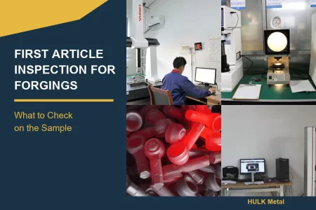
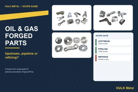
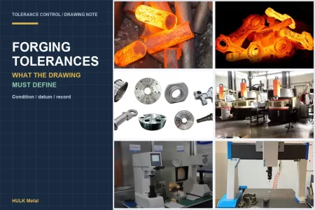
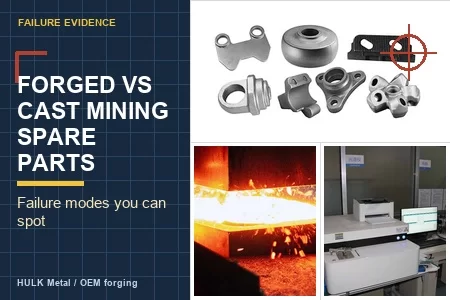
These articles help a buyer move from product selection to a more reviewable order. They cover pressure-boundary scope, oil-and-gas terminology, forged-versus-cast evidence, drawing tolerance release and first-article checks. Use them to prepare the drawing, inspection and supplier-qualification questions that belong in the flange or hub RFQ before the buyer asks for a price and a committed delivery plan.