The review starts with impact, abrasion, mounting and replacement conditions, so the forging route follows the part's field task instead of a stock-model guess.
OEM Geometry, Not Stock Models
Agricultural forging parts are produced to the buyer's current drawing. There is no standard catalogue, fixed size list or assumption that one tillage profile fits every machine.
Drawing-Controlled Material Route
Carbon, alloy and stainless steel options are reviewed against the drawing. The selected grade, processing condition and acceptance basis remain tied to the approved revision.
Outsourced Heat Treatment, Visible Records
Heat treatment is carried out by an audited partner. The released lot can be tied to the required process record, sample identity and inspection result.
First-Lot Release Before Volume
The first production lot is checked for drawing revision, material heat, forging lot, returned-pack identity, dimensional result, required tests and signed disposition.
This table separates generic OEM scope from values that change with the drawing. It is a review map, not a stock specification sheet. Dimensions, grades, heat-treatment conditions, sampling and acceptance limits are confirmed for the order.
Attribute
OEM agricultural forging route
Confirmation basis
Part families
Tillage points, blades, wear bars, brackets and related forged hardware
Drawing and working position
Material
Carbon steel, alloy steel or stainless steel
Grade per drawing
Forging route
Hot die forging with induction heating
Drawing and order review
Machining
As-forged or drawing-defined machined features
Finished-part drawing
Heat treatment
Outsourced to an audited partner
Process specification per drawing
Inspection
In-house dimensional, hardness and batch-record checks
Drawing and acceptance plan
Certificate
ISO 9001
Only certificate claim on this site
MOQ and lead time
Confirmed for the drawing and order
Contact us for details.
Agricultural Forging Parts Made to Your Drawing
This page explains how an agricultural wear part moves from the working position and drawing review into a controlled hot die forging route, outsourced heat treatment, inspection and first-lot release. It also sets clear exclusions so the buyer can send a usable RFQ, compare the same scope and avoid treating an illustrative catalogue image as a stock model.
HULK Metal makes OEM agricultural forging parts to the buyer's drawing. The workable route starts with the field-wear position, then connects drawing revision, material, forging lot, outsourced heat treatment and first-lot release.
There is no stock catalogue of standard tillage points and no assumption that one profile fits every machine. The drawing and operating condition decide the geometry, material, inspection route and commercial terms.
Agricultural equipment usually asks the forged part to survive abrasion, impact, bending and repeated assembly. A buyer can name the part a plow point, wing, wear bar or bracket, yet those words do not define the working edge, mounting face or wear direction. That is why the drawing review begins with function rather than a catalogue name.
Agricultural Forging Parts Start with the Field Wear Position
A field-wear position tells the supplier where material loss, impact and load enter the part. It also shows which surface must remain stable enough for replacement, alignment or assembly.
Material behavior changes when the drawing moves the load from a narrow point to a bolted bracket. A hard cutting edge with an unsupported mounting face may release from the tool bar before the edge reaches its wear limit. A thick bracket with a poorly defined locating face may survive impact but create assembly variation.
Working surface
The point, edge, wing or bar that meets soil, crop residue or impact first.
Load path
How force travels from that surface into the mounting holes, shoulders and supporting body.
Replacement interface
The faces, holes and references that let the buyer fit the new part without reworking the machine.
Representative tillage point: define the soil-engaging face, replacement fit, mounting holes, supporting shoulder and any machining boundary. A representative image on this page is illustrative; the ordered geometry remains the current buyer drawing.
Representative wear bar or blade: define which edge wears, which face locates the part, and whether the drawing allows as-forged edges, machining or a prepared cutting profile.
Representative bracket or forged hardware: define hole position, datum faces, section transitions and the load path between the fixing points. The image family is illustrative; the order is not selected from stock.
Table 1. How the field task changes the drawing review.
Part family
Primary field task
Drawing evidence
Release evidence
Point or tip
Enter soil and lead the wear path
Working face, point angle and mounting fit
Profile, fit-up and required surface checks
Blade or wear bar
Resist abrasion and retain a useful edge
Wear direction, edge condition and support face
Edge form, straightness and drawing dimensions
Bracket or link
Transfer impact into mounting points
Datum, holes, shoulders and section changes
Hole pattern, datum dimensions and records
Send the worn part only as a supplement. The primary input is still the controlled drawing, because a worn sample cannot show the original datum, machining allowance, material condition or acceptance basis.
Forged Tillage Points and Blades Need a Different Drawing Review
Tillage points, blades and wear bars are not reviewed as one generic shape. Their wear surface may be small, but the forging contains a load path that reaches the mounting interface.
On a point, the front profile controls penetration and wear. The rear fit controls whether the part seats correctly. On a long wear bar, straightness and support faces may matter more than the aggressive-looking edge. On a bracket, the holes and datum faces carry the consequence of every upstream radius and section change.
Drawing gate
A photograph or a worn sample cannot replace the forging drawing. It can show the service result, but it cannot define the original datum, dimensions or heat-treatment condition.
Questions that belong on the drawing review
Which face wears first? This decides where material must be preserved and where machining may be allowed. Which face locates the part? This decides which datum and mounting features cannot move during forging or correction. Which features are forged, machined or left as a reference? This prevents a nominal shape from being accepted when its functional face is incomplete.
How is the part replaced? A forged point with the wrong eye width or hole spacing creates downtime even if the tip profile looks correct. The buyer should show the mating component or the installed reference when replacement is the task.
1
Mark the engaged surface. State where soil, crop, stone or another machine feature contacts the part.
2
Mark the mounting datums. Identify holes, slots, shoulders or clamps that control installation.
3
Define the failure consequence. State whether wear, bending, cracking, loss of fit or assembly variation is the main reject concern.
4
Close the acceptance route. Confirm the dimension, hardness, test and record requirements that release the first lot.
What HULK Metal Can Produce for Agricultural Equipment
HULK Metal can review OEM agricultural forging parts such as tillage points, blades, wear bars, brackets and related forged hardware. Capability means the part may enter a drawing review; it does not mean every drawing automatically passes.
Table 2. Scope before quotation.
Can enter drawing review
Must be confirmed
Outside this page's scope
Tillage points and replaceable tips
Working profile, mounting and material
Standard stock models
Blades, edges and wear bars
Wear face, support and edge condition
Cold forging and ring rolling
Forged brackets and mounting hardware
Datums, holes, section changes and records
Gears, shafts and spindles
Carbon, alloy or stainless steel per drawing
Grade, heat treatment and acceptance
Aluminium, titanium and prohibited grades
Capital equipment, forestry tools and tractor-mounted implements may be valid working environments for these parts. The page does not extend that scope into automotive assemblies, medical equipment, chemical processing or unrelated high-precision applications.
Outside the drawing-review list, no product becomes a stock alternative. Gears, shafts, spindles and other excluded categories stay outside the HULK Metal capability list and should be sourced through a different supplier route.
Material Selection Follows the Drawing and Working Condition
The material decision begins with the buyer's grade and required condition. Carbon steel, alloy steel and stainless steel can be reviewed, but the drawing and purchase specification must say which grade applies and what acceptance follows it.
A wear part may need a hard working surface, but hardness alone does not describe the complete requirement. The part also needs enough support to resist bending, a heat-treatment route that suits the material, and a sampling plan that confirms the result in the correct location. A hardness reading at an easy location can miss the surface that actually works in the field.
Heat-treatment boundary
HULK Metal uses an audited partner for heat treatment. We do not describe the process as in-house. The hardness band, case depth, sampling position, test method and acceptance basis remain per drawing or confirmed on request.
Why the grade cannot be chosen from “wear part” alone
Two parts performing the same visible task can carry different load. A small point may see concentrated impact at the tip. A long edge may bend across its support span. A bolted bracket may crack at a hole or section transition before abrasive wear becomes visible. The drawing needs to show which condition governs.
A buyer should also identify the replacement strategy. A low-cost sacrificial wear part may intentionally give up material at a controlled surface. A reusable mounting body may need tighter protection against deformation. Neither choice can be inferred from the phrase “agricultural forging.”
Where an existing material is mandated, send its grade and revision. Where the buyer is still selecting, describe the working position, contact material, replacement interval and failure mode so the material discussion has a basis. The final material grade and process remain drawing-controlled.
Where Agricultural Forgings Fail in Service
Most field failures have a visible or record-level clue before the part reaches the end of its useful life. The clue may be incomplete die fill, a lap, a crack along the flash line, surface scale, a bent mounting face or a hardness record that cannot be tied to the returned lot.
Failure-board language should not promise that a forged part will never fail. It gives the buyer and supplier a common way to describe the symptom and the first check before deciding whether the drawing, tooling, material or process needs change.
Table 3. Field symptom, forging mechanism and first verification point.
Symptom
Possible forging mechanism
First check
Tip or thin rib not filled
Billet volume, temperature or blocker distribution leaves the die cavity incomplete
Compare the missing area with the die layout and billet allocation
Fold or seam near a shoulder
Metal turns back into the body at a tight radius or from an unstable preform
Inspect the preform flow and die radius against the drawing
Crack along the flash line
Trim timing, clearance or stress concentration at the flash line
Review trim condition and the edge appearance after trimming
Pits after blasting
Oxide scale is pressed into the surface during deformation
Trace heating, descaling and die-cavity condition
Hole pattern or face shifted
Die mismatch, wear, billet placement or correction drift
Check datum dimensions and the fixed direction of the shift
Hardness or distortion issue
Section change, residual stress or an unsuitable outsourced heat-treatment route
Connect the returned part to its process load, sample and test result
Underfill at the working end
If the missing metal repeats at the same tip position, the cause usually follows the die cavity rather than a random handling accident. Confirm the billet allocation, temperature and preform before changing the finished drawing.
Lap or cold shut around a section change
A fold contains metal that did not bond into the surrounding body. A cold shut follows converging flow that cooled before closure. Both need the die and process review, not cosmetic polishing without a source decision.
Wear that becomes a mounting failure
A worn point can still be rejected because the mounting eye, clamp face or support shoulder no longer locates the replacement. The drawing should identify which surfaces control replacement, and inspection should treat them as acceptance features.
Can a picture of the broken part replace the original drawing?
No. The controlled drawing still governs datum, material and release.
Does one hardness reading release the whole lot?
Only when the drawing and approved sampling plan say so. The sample location, test method, process load and lot relationship must be clear enough to show that the reading represents the specified section rather than an easy surface.
What if the part is visibly worn but the mounting face remains intact?
Compare the wear result with the intended working surface and replacement interval. A clean mounting face does not prove the working surface met the required condition. The field observation, drawing requirement and replacement strategy need to be reviewed together before the design is accepted.
The Drawing Gate: What Must Be Fixed Before Tooling
A usable OEM drawing lets the supplier separate nominal forged geometry from finished-part requirements. It also gives inspection a basis that does not change after the first sample.
Buyer input does not need to reveal proprietary design intent, but it must identify the revision and the condition in which the dimensions apply. A dimension marked on a finished surface has a different meaning when the order is supplied as-forged.
Two drawings, one decision
If the buyer supplies a forging drawing and a finished-part drawing, both belong in the RFQ. The supplier must know which surfaces are forged, which are machined and which controls release.
Table 4. Drawing input, production consequence and buyer action.
Drawing input
Production consequence
Buyer action
Parting line and draft
Controls die opening, material flow and the forged surface
Approve the forging drawing, not only the finished shape
Machining allowance
Determines how much material remains after forging
State the allowance basis and machining scope
Datum and mounting features
Controls replacement fit and inspection setup
Identify which datums are functional
Section changes and radii
Affects fill, laps, stress and tooling
Flag sharp changes and required blending
Material and heat treatment
Sets process route, records and test requirements
Provide grade, condition and sampling basis
Inspection and NDT basis
Defines acceptance and rejection
Name the method, area and acceptance authority
A drawing review also protects the buyer from a false comparison. Two suppliers may quote the same part name while one is pricing an as-forged blank and the other is pricing a machined, heat-treated part with an inspection dossier. Those offers are not equivalent.
Where a value cannot be supplied at the RFQ stage, the drawing or approved acceptance plan must define how it will be confirmed. A critical dimension, hardness band, sampling position or NDT level cannot be left to a verbal promise after production.
How the Forging Route Protects the Wear Surface
Hot die forging shapes the part while the metal is heated. Induction heating shortens the exposure before deformation, and the die sequence controls how metal reaches the working surface and the mounting body.
A
Receive and identify material. The material heat is linked to the order before the billet is cut.
B
Heat and form. Induction heating and the approved die route are followed for the forging condition.
C
Trim and correct. Flash removal, form correction and surface condition are checked against the process plan.
D
Route treatment and inspection. Any outsourced heat treatment returns with the identity needed for the release decision.
Grain flow matters because the hot deformation route can turn the metal structure to follow the part geometry. The benefit is not a slogan; it is a reason to keep the working face, support body and mounting transition in the same controlled forging design.
Part shape also changes the route. A thin point, a long bar and a thick bracket may need different blocker or finisher arrangements. Changing the apparent wear profile without reviewing the preform can move the risk from the field edge to a fold, an unfilled section or a crack at the flash line.
Factory Insider: What We Check Before Releasing a Wear-Part Lot
On our production floor, the release review begins with the identity chain. A good-looking first part does not compensate for a missing material heat, process load or inspection record.
We compare the current drawing revision with the part in hand, then follow the material and batch identity into the inspection record. For an outsourced heat-treatment step, we expect the returned lot to remain traceable to the process specification, sample identity and required test result.
What we will not treat as proof
A photograph of a similar part, an unsigned statement that the process was controlled, or a test result that cannot be connected to the furnace load does not close the first-lot release.
We also look for the field failure the part is most likely to create. A sharp point may expose underfill. A tight support transition may expose a lap or crack. A long wear bar may expose correction and dimensional drift. The inspection plan should name the consequence, not only the process.
How to Release the First Agricultural Forging Lot
First-lot release is a supplier-approval event. It should prove that the drawing, material route, process record, inspection result and returned parts belong to the same production decision.
0 of 8 checked
If a record is missing, the lot should not be released by assumption. The buyer and supplier need to identify which lot, sample and decision are affected. Corrective action starts from the broken identity chain, not from a new visual inspection alone.
Use the first lot to improve the interface for volume. If a mounting face is difficult to inspect, a sample is hard to identify after treatment or the pack label does not survive the process, fix that before increasing the order.
What to Put in an Agricultural Forging RFQ
A useful RFQ lets the supplier answer two questions: can the part enter the OEM forging route, and what evidence is required to release it? A general part name alone cannot answer either question.
Technical packet
Current drawing revision, working position, material grade, heat-treatment condition and inspection basis.
Commercial packet
Order split, destination, packaging and any delivery sequence that affects the production plan.
Release packet
First-lot approval rule, required reports, sample position and the person or process that accepts deviation.
Ready to review
Send the drawing, wear position, material condition, inspection basis, order split and destination. We will review the OEM agricultural forging route and identify any missing input before quotation. Contact us for details where the drawing does not yet define a value.
Can HULK Metal supply a standard tillage point from stock?
No stock-size tillage catalogue is offered.
Can gears, shafts or spindles be added to this page quotation?
No. Those categories are outside the HULK Metal capability list. This agricultural page is limited to the stated OEM wear-part and forged-hardware scope, with no exception created by a mixed RFQ.
Can the supplier confirm hardness before receiving the drawing?
No fixed hardness value is quoted here. Material grade, heat-treatment condition, sampling position and acceptance basis remain per drawing or confirmed on request.
Review the drawing before the first cut
Fix a missing datum, an undefined heat-treatment basis or a weak mounting interface before tooling and the first production lot. HULK Metal reviews the OEM route against the current drawing; the drawing remains the controlling document.
Quality Control: What We Test and How
Quality control follows the approved drawing and order requirements. The inspection plan should connect incoming material, forging, any outsourced heat treatment, finished dimensions, required mechanical or surface tests and packing. Test values, sampling positions and acceptance levels are per drawing or confirmed for the order.
Raw Material Inspection
Material grade and heat identity are checked before release to production. Chemical composition is reviewed with the incoming record, and any mismatch with the drawing or purchase requirement stops the lot.
Production Inspection
Induction heating, billet placement and die condition are monitored through the agreed process plan. Operators check the working end, mounting area and flash-line condition for underfill, laps, scale or visible cracking.
Dimension Inspection
Dimensions are measured against the controlled drawing and datum scheme. Allowance, tolerance, hole pattern and critical faces follow the order; unsupported values are not invented in process. The inspection record states the measured characteristic and its relation to the approved drawing.
Mechanical and Hardness Verification
Where the drawing requires hardness, tensile or impact evidence, the lot is tied to the outsourced treatment record and approved sample. The location and method are confirmed before testing; the supplier does not invent a universal acceptance value.
Surface Inspection
Rolled-in scale, deep pits, laps, cracks and other surface conditions may affect the wear surface or mounting face. Acceptance follows the drawing and approved inspection basis. The lot is held when a visible condition exceeds that basis.
Finished Product Inspection
Finished features, identification and required records are checked as one release package. The reviewer confirms that the returned part can be connected to the forging lot, treatment record, sample and disposition.
Packaging Inspection
Pack labels, quantity, protection and document placement are checked before shipment. The pack must preserve the identity needed to connect the buyer's receipt to the released lot and required records.
AGRICULTURAL FORGING FACTORY AND WORKSHOP ROUTE
The factory route combines material control, induction heating, die forging, outsourced heat treatment, in-house inspection and packing. Each step keeps the identity needed for the buyer's first-lot release and the next technical review.
Production Workshops
Manufacturing Equipment
Inspection Center
Warehouse
Packaging
Surface Treatment Center
Production Workshops
Worksheets, dies and forged lots move through an organised hot-forging route. The production team starts from the approved drawing and order split, then records the material heat, process route and batch identity before parts move to the next operation. The workshop review also checks that the die being set belongs to the current drawing revision.
Manufacturing Equipment
Induction heating and multiple forging presses support the OEM hot die forging route. Equipment selection follows the part shape and drawing rather than a fixed catalogue model; tonnage is not published and is not used as a buyer-facing promise. Any change to the die sequence or billet plan is reviewed before the first production lot.
Inspection Center
The inspection center checks material, dimensions, hardness, surface condition and required reports against the approved plan. The review connects each result to the material heat, forging lot and finished pack so a missing record becomes a controlled hold. The drawing and approved acceptance basis remain the controlling documents for every measured characteristic and every release record.
Warehouse
Incoming material and completed parts are stored with identification attached to the order and lot. Storage keeps forged parts separate from unrelated production and protects the marking needed to trace a part back to inspection and packing documents. The lot identity remains visible through warehouse transfer, sorting, final release, shipment handoff, carrier pickup and document archive.
Packaging
Packaging follows the agreed quantity, protection and destination requirements. Labels are checked against the release package, and the buyer's receipt can be connected to the same lot reference used during fabrication and inspection. Packing protects working edges, mounting faces and visible identification from damage before shipment. The packed quantity and document set are checked at the final release point.
Surface Treatment Center
Surface treatment is selected from the drawing and order requirement. Cleaning, coating or other finishing follows the approved route and is checked before packing; exact treatment and acceptance are confirmed for the drawing and order. Surface work never replaces the required dimensional, material or process records. The finishing record remains part of the same released lot.
BENEFITS CHOOSE HULK METAL AS YOUR AGRICULTURAL FORGING PARTNER
The value is a single OEM route from drawing review to first-lot release, with clear exclusions and traceable boundaries around material, heat treatment, inspection and packing. It keeps the technical and commercial discussion on the same approved scope.
One Stop Purchase
HULK Metal coordinates drawing review, material, hot die forging, machining where required, outsourced heat treatment, inspection and packing through one responsible contact. The buyer does not need to invent a second route between a forged blank, a treatment supplier and a document set. The same release reference follows the part from the approved drawing to packing and receipt, giving the buyer one accountable commercial and technical contact.
Get Higher Quality
Quality starts with the drawing and material identity, continues through induction heating and die forging, and closes with batch inspection. ISO 9001, in-house dimensional checks and defined records support the release decision without claiming unsupported certificates. The inspection plan follows the drawing, including heat-treatment, sampling and acceptance evidence, so the buyer can review the same technical basis used for production.
Get Faster
A complete drawing packet lets the supplier review the tooling and inspection route earlier. Clear datums, material grade and acceptance basis reduce late clarification, while the production plan still depends on quantity, tooling and order conditions. Fewer missing inputs mean fewer repeated technical reviews before production or sample approval begins, and the first lot can move through inspection with fewer open questions.
Save More Money
The total route is evaluated as forging, material, machining, treatment, inspection and freight. Fixing the drawing before tooling avoids hidden rework from an incomplete wear face or mounting interface, even when the lowest initial quote appears cheaper. The goal is a stable, traceable production route rather than the lowest untested starting price, with fewer unplanned loops after the first sample.
Save More Time and Energy
One release chain connects the drawing, lot, process record and inspection result. The buyer spends less time reconciling emails and more time evaluating the first sample, field fit and next production decision. A clear hold point also prevents doubtful parts from moving forward before the record and disposition are resolved. The result is a cleaner handoff from engineering review to procurement.
RELATED FORGING GUIDES FOR AGRICULTURAL PART BUYERS
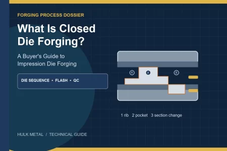
These guides explain the drawing, tooling, tolerance and first-article evidence behind an OEM agricultural forging order. Start with closed-die process basics, then review the drawing details that set tooling and inspection. The tolerance and first-article guides show how a sample is released without inventing acceptance values. Use them to prepare a clearer RFQ before asking for the first quotation or comparing suppliers.