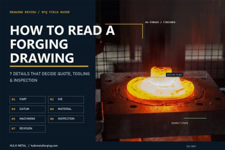
The review starts with the pressure boundary, end connection and functional faces, so the die and machining plan follow the valve duty instead of a generic part label.
Pure OEM Geometry
Forged valve parts are produced to the buyer's drawing. There is no stock valve catalogue, fixed pressure class or assumption that an older part remains interchangeable.
Drawing-Linked Treatment Route
Material grade and heat-treatment condition remain tied to the approved drawing. The separate treatment step returns with lot identity for inspection and first-article review.
Forging Defects Made Visible
Underfill, laps, cold shuts, flash-line cracks, mismatch and scale condition are checked by location and process state so corrective action starts from evidence.
Traceable First-Article Release
Drawing revision, material heat, forging lot, outsourced treatment, dimensions and required NDT meet in one sample package before serial production begins.
This review map separates the confirmed OEM process from values that change with the valve drawing. Pressure class, dimensions, material grade, treatment, inspection and commercial terms remain order-specific and are not borrowed from a stock catalogue.
Attribute
OEM valve-forging route
Confirmation basis
Part scope
Valve bodies, valve stems and related valve flanges
Drawing and approved capability scope
Material
Carbon steel, alloy steel or stainless steel
Grade per drawing
Forging
OEM hot die forging with induction heating
Drawing and process review
Machining
As-forged or drawing-defined machined features
Forging and finished-part drawings
Heat treatment
Outsourced to an audited partner
Process specification per drawing
Inspection
Material, dimensional, hardness, tensile and visual checks as required
Drawing and approved inspection plan
NDT
Method, coverage and acceptance set by the buyer
Purchase specification
Certificate
ISO 9001
Only certificate claim on this site
Pressure class and tolerances
Per drawing
Controlled drawing and specification
MOQ and lead time
Confirmed for the drawing and order
Contact us for details.
Forged Valve Parts Made to Your Drawing
This page shows how an OEM valve body, valve stem or related valve flange moves from the buyer's drawing into a pressure-boundary review, hot die forging route, outsourced heat treatment, inspection plan and first-article release. It also separates evidence from assumption, because a valve-part page is useful only when the drawing and order can still control every critical value.
HULK Metal reviews OEM forged valve bodies, valve stems and related valve parts against the buyer's drawing. Pressure class, end connection, material condition, heat treatment, dimensions and inspection stay with the approved drawing and order.
The route uses induction heating and multiple forging presses, with outsourced heat treatment and in-house inspection. HULK Metal does not turn the words “valve” or “oil and gas” into an assumed pressure rating, material grade or inspection level.
Pressure-boundary release map
Valve Body, Stem and Pressure-Boundary Parts: What This Page Covers
The commercial scope is a forged valve-part family, not a catalogue of finished valves. The buyer supplies the controlled geometry and required condition; the supplier reviews whether the part can enter the OEM hot die forging route.
A valve body carries the pressure boundary and contains the flow path. A valve stem transmits movement to the closure element. A related valve flange provides a connection interface. Each part can share a material family while needing a different die, datum scheme and inspection emphasis.
Valve body
Review the pressure boundary, section changes, end connections, machining stock and surfaces that remain as-forged.
Valve stem
Review straightness, transition zones, grip or actuation features and the inspection state requested by the drawing.
Related valve flange
Review the connection interface, sealing face, bolt pattern, heat-treatment condition and final machining boundary.
What this page does not promise
There is no stock valve catalogue, no fixed pressure class, no universal material grade, no standard hardness window, no default NDT level and no published MOQ or lead time. Values not present in the drawing remain open until confirmed.
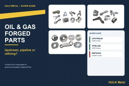
The scope also has hard edges. Gear and general shaft production is outside the HULK Metal capability list, even though a valve stem is a named valve-part component. Refining and petrochemical process-equipment scope is outside the approved oil-and-gas boundary. Aluminium forging, cold forging, ring rolling and forged wheels are not offered.
Send the drawing before asking for a valve-body quotation. A photograph of an installed valve may explain the application, but it cannot replace the drawing revision, material requirement, acceptance basis or machining scope.
How Valve Function Becomes a Forging Decision
The first decision is not the press setting. It is which part of the drawing carries pressure, which surfaces control assembly and which material is removed after forging.
A valve body may look like one enclosed block, but the drawing can contain several competing jobs. The cavity must form, the wall must support the intended boundary, the end connection must remain machinable and the die must open without trapping metal. These requirements interact before tooling is released.
1
Identify the controlled part. Record the drawing revision, part number, supplied condition and whether the drawing describes a forging or a finished part.
2
Mark the pressure boundary. Identify the surfaces and sections whose continuity matters to the valve function, not only the outer envelope.
3
Separate forged and machined features. The die shape protects some faces; other faces depend on later machining and must retain enough stock.
4
Resolve material and treatment. Grade, incoming condition, heat treatment and hardness basis must point to the same released requirement.
5
Build the acceptance plan. Dimensions, sample location, NDT and first-article records follow the drawing and purchase specification.
A finished-part drawing can be enough to start engineering review, but it does not automatically define the forging. The supplier still needs a workable separation line, draft, fillets, machining allowance and release condition. If those choices remain implicit, two quotations may use different assumptions while showing the same finished outline.
The pressure boundary also changes what “critical” means. A cosmetic outer face may remain broad machining stock. A narrow internal transition may decide whether the die fills or folds. The review should therefore classify features by function and process state, not by drawing appearance alone.
Drawing state is part of the price
An as-forged body, a machined body and a body released with heat-treatment and NDT records are different purchase scopes. The drawing and order must state which one is being quoted.
Pressure Class, End Connection and Section Shape: The Three-Way Review
A pressure class is a specification input, not proof that one forging plan fits every valve. The body material, wall geometry, end connection, trim interface and acceptance plan must be reviewed together.
The buyer's drawing or purchase specification may name a project pressure class or a governing valve standard. HULK Metal does not infer feasibility or acceptance from that label. The drawing must show how the class becomes geometry and how the required tests are applied.
Pressure class controls the evidence request
Start with the pressure boundary, the material condition and the required inspection. A class label alone does not define wall stock, sampling, NDT coverage or acceptance. Those values must be traceable to the buyer's specification and drawing revision.
End connection controls the machining boundary
The connection type determines which surfaces remain forged and which are completed later. It can also change the inspection setup, because a datum taken from one end may not control the opposite interface in the same way.
Section shape controls fill and die release
Thick hubs, thin webs, offset bosses and long transitions compete for metal flow. The forge review asks where material must be added, where a blocker impression may help and where the parting line can remain practical.
Table 1. Valve forging inputs and their consequences.
Drawing input
What it changes
Buyer action
Pressure class or governing specification
Required material, test and acceptance evidence
Provide the exact revision and contractual reference
End connection
Machining boundary, datum access and inspection fixture
Mark which faces remain as-forged
Body section
Billet distribution, blocker need, fill and trimming
Show minimum forged stock and functional transitions
Stem interface
Transition geometry, straightness and final condition
Define actuation and closure interfaces
Material condition
Heating, deformation and outsourced treatment route
State grade, supplied condition and heat-treatment requirement
A higher class label does not by itself prove that a larger die, a different material or a specific NDT method is required. The technical result follows the drawing and specification. If those documents conflict, the conflict must be resolved before tooling because a supplier cannot inspect two different acceptance bases as if they were one.
The most comparable RFQ separates three groups: pressure-boundary requirements, connection and machining requirements, and commercial conditions. That prevents a low quotation from hiding a narrower scope, such as an as-forged blank with no treatment records or final inspection.
Materials and Heat-Treatment Routing for Forged Valve Parts
Material selection begins with the buyer's grade and service requirement. Carbon steel, alloy steel and stainless steel can be reviewed, but the selected grade and delivered condition remain drawing-controlled.
The same grade name can appear in several delivery conditions. A normalized part, a quenched-and-tempered part and an as-forged part are not interchangeable. For valve components, the treatment requirement must connect to the pressure boundary, the final machining operation and the specified test location.
Table 2. Material and process questions for an OEM valve-part quotation.
Decision
What the drawing should define
Why it matters
Grade family
Carbon, alloy or stainless steel grade
Controls material purchase and incoming verification
Delivery condition
As-forged, normalized, annealed or quenched and tempered
Changes the treatment route and inspection sequence
Hardness basis
Required band, test location and sampling rule
Prevents a convenient reading from replacing the specified result
Mechanical evidence
Required test and sample relationship
Connects the result to the approved material and lot
Surface condition
Cleaning, descaling or coating requirement
Defines what is inspected before packing
NDT basis
Method, coverage and acceptance authority
Keeps acceptance with the buyer's specification
Grade
Confirm the buyer's grade and permitted equivalent basis.
Incoming identity
Link the material heat to the order and production lot.
Forging
Use induction heating and the approved die and process route.
Outsourced treatment
Return the treated lot with the required process record.
Heat treatment is performed by an audited partner. It is not described as an in-house furnace operation. The handoff matters because quenching, tempering, normalizing or another specified route can change hardness, dimensions and residual stress. The return record must stay connected to the material and forging lot before inspection can close the sample.
Material substitution is not automatic. If the drawing permits an equivalent, the proposed grade still has to be reviewed against mechanical requirements, treatment response and buyer approval. A familiar grade name does not prove that it belongs to the current valve part or order.
Useful material note
Write “material grade per drawing” when the grade is not yet fixed. Do not use a hardness band, pressure rating or test level copied from another valve project as a substitute.
Grain Flow, Parting Line and Machining Allowance in Valve Body Forgings
Grain flow is useful only when it follows the load path that remains after machining. A die can form a sound outer envelope while later cuts remove the very material direction the design intended to preserve.
A valve-body hub, neck and branch can direct metal into different local flows. The die designer has to balance those flows against fill, laps, trimming and the parting line. The buyer's drawing should identify which regions are structural and which surfaces may be machined without changing the intended route.
Flow direction
Material displacement should follow the body, branch and load path rather than stopping at a visual outline.
Parting line
The line must support die opening, trimming and inspection without placing it on an uncontrolled sealing face.
Machining stock
Enough stock must remain for the finishing route while avoiding metal that only adds cost and distortion risk.
Read the forging drawing as a removal plan
If the finished drawing shows a flat face, the forging drawing must show how much material sits above it and how that face will be established. The same logic applies to bores, bolt holes and connection faces. “Leave stock” is not a complete instruction when the amount and datum are still open.
A split between forging and machining also prevents a false first-article result. A dimension checked on the forged body before machining is not the same acceptance result as the finished interface. The report must state the inspection state.
Table 3. Valve-body geometry, process risk and release question.
Geometry
Process risk
Release question
Thin web between cavities
Underfill or excessive chilling before closure
Does the die leave enough section and stock?
Offset boss or neck
Lap, mismatch or difficult trimming
Is the transition and parting line practical?
Deep machined cavity
Insufficient remaining wall or distortion after treatment
Which surfaces define the final boundary?
Closely spaced holes
Forged stock and datum access conflict
Are they forged, pierced or drilled later?
Sealing or connection face
Wrong inspection state or incomplete machining stock
Which operation creates the accepted face?
The strongest drawing review leaves the fewest hidden decisions. A supplier should not infer the parting line from a finished model, choose machining allowance as a house convention, or decide unilaterally that a difficult feature will be added later without the buyer's approval.
If the drawing allows a forging method only in general terms, send the 3D model and the functional requirements together. That lets the review compare die closure and metal flow with the faces that must remain after machining.
Failure Modes Buyers Should Read Before Approving a Die
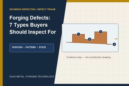
A valve-body reject should be described by position, pattern and process state. “Bad surface” is not enough to decide whether the die, billet, heating route, trimming or treatment needs action.
Defects that repeat in the same cavity location usually point toward tooling or metal distribution. Defects that vary with heat, transfer time or handling point toward process control. A mixed description sends the investigation in the wrong direction.
Underfill at a branch or narrow web
Short fill that repeats at the same local feature can come from insufficient billet volume, low local temperature or high die resistance. Review the blocker impression and material distribution before changing only the finished geometry.
Lap or cold shut around a transition
A lap contains a folded surface; a cold shut follows converging metal that failed to close. Both need a die-flow and temperature review because polishing the visible mark does not restore the internal condition.
Crack at the flash line
Trimming temperature, die clearance and flash-gutter design can concentrate stress along the edge. The inspection note should record the location and whether the indication remains after the approved cleaning operation.
Table 4. Failure evidence and the first controlled response.
Observation
Possible cause
First response
Short fill at one repeatable location
Die resistance, billet allocation or local temperature
Hold the lot and review the preform and die condition
Fold or discontinuous flow line
Poor metal convergence or sharp transition
Inspect the die and sample before accepting cosmetic repair
Crack along trim edge
Trimming condition, clearance or material sensitivity
Record depth, direction and process state
Mismatched halves
Die alignment or billet offset
Check repeated direction across the parting plane
Scale pits after cleaning
Oxide pressed into the surface during forming
Connect the location to heating and descaling practice
Distortion after treatment
Residual stress or an unsuitable treatment route
Compare the before/after state and treatment record
Does a visual crack always mean the die is wrong?
No. Record the location, direction and process state first.
Can a photographed defect replace a physical sample review?
A photograph can preserve the position, but it usually cannot show depth or internal continuity. A useful review connects the image to the material heat, forging lot, treatment state and the inspection method named by the drawing. The photograph is evidence about appearance, not authority to release the part.
Should every surface mark be rejected?
Use the drawing and accepted surface basis. A mark becomes a decision point when it exceeds that basis or lacks a controlled rework path.
Factory Insider: How We Read a Valve Drawing Before Tooling
On our production floor, we start by asking what the finished valve part has to do, then work backward to the forging shape. A drawing that looks closed on screen can still leave the die opening, datum and acceptance state unresolved.
We compare the current revision with the material note and the inspection requirement before tooling is committed. If the part is heat treated by an audited partner, the return identity and requested result are planned into the route from the beginning.
First, separate the jobs
The pressure boundary, connection face and actuation interface may require different controls. Treating every face as equally critical hides which ones actually drive the die.
Second, protect the flow path
We check whether the parting line and machining stock preserve the intended flow around the body and branch, rather than cutting away the useful structure.
Third, connect the release records
A first article is useful when the drawing, material heat, forging lot, treatment record and inspection result point to the same sample.
Fourth, stop at ambiguity
If pressure class, grade, condition or acceptance remains contradictory, we keep the value open rather than turning a verbal assumption into a production promise.
We also challenge the “same as the last part” shortcut. A new size, end connection or treatment requirement can change billet distribution, tooling and inspection even when the outside shape looks familiar. The drawing package has to make that difference visible.
The review ends with a working list: which features remain forged, which become machined, which material and treatment records are required, which dimensions are checked in each state and which samples or NDT reports belong to the first-article decision.
Inspection and First-Article Release for Valve Bodies and Stems
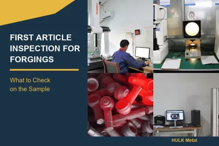
First-article inspection is a release gate. It asks whether one controlled sample proves that the die, material route, outsourced treatment and inspection plan are ready for the next production decision.
A good-looking valve body does not compensate for a missing drawing revision or a treatment record that cannot be connected to the lot. The sample must be measurable against one datum scheme and identifiable through the production records.
0 of 8 checked
The inspection state is easy to lose when several operations follow forging. A feature measured after machining cannot be compared with the same nominal feature measured as-forged unless the drawing and report make the change explicit. The same rule applies after outsourced heat treatment, where distortion and scale condition can alter the result.
For NDT, the buyer chooses the method, area and acceptance level. HULK Metal does not infer a UT, MT or PT acceptance class from “valve” or “oil and gas.” The approved inspection plan should make coverage and disposition clear before the first lot is produced.
RFQ Checklist: What to Send for a Forged Valve Quote
A complete RFQ lets the supplier compare the same technical and commercial scope. A part name and a picture may reveal the product, but they do not define the forging route or release evidence.
Include the controlled drawing, 3D model where available, supplied condition, material grade, treatment requirement, inspection basis and destination. State whether the quotation covers as-forged, machined, treated, inspected and packed scope.
Geometry packet
Drawing revision, model, datum and tolerance scheme, pressure-boundary features, end connections and machining boundary.
Material packet
Grade, incoming condition, heat-treatment result, hardness basis and any permitted equivalent.
Acceptance packet
Dimensional plan, required tests, NDT method and level, first-article rule and deviation authority.
Ready to review
Send the drawing, model, pressure-boundary features, material and treatment requirement, inspection basis, order split and destination. We will identify any missing input before quotation. Use “Contact us for details.” where no controlled value exists.
Can HULK Metal quote a standard valve body from stock?
No stock catalogue is offered. Every quotation starts from an OEM drawing and order condition.
Can a general shaft be added to the same valve-part order?
No. General shafts remain outside the capability list even if they appear near the same valve assembly. A valve stem is reviewed only as a named valve-part component within the approved OEM scope.
Can the pressure class be inferred from an installation photo?
No. The drawing, purchase specification or approved order documents must define pressure class and acceptance.
Does HULK Metal perform heat treatment in-house?
No. Heat treatment is carried out by an audited partner. The return handoff should identify the treated lot and connect it to the requested process condition, sample identity and inspection requirement before release can continue.
Review the pressure boundary before the first tool cut
A valve-body forging is ready for quotation when the drawing identifies the part, material condition, pressure-boundary features, end connections, machining boundary and acceptance route. HULK Metal reviews that OEM scope; the approved drawing remains the controlling document.
Quality Control: What We Test and How
Quality control follows the approved drawing and order. The inspection plan connects incoming material, forging, outsourced treatment, dimensions, required mechanical or NDT checks and packing. Test values, sample positions and acceptance levels are per drawing or confirmed for the order; ISO 9001 is the only certificate claim.
Raw Material Inspection
The material grade and heat identity are checked against the order before production. Chemical composition can be reviewed with the spectrometer, and a mismatch with the drawing or purchase requirement stops the lot before billet preparation.
Production Inspection
Induction heating, billet placement, die condition and trimming are monitored through the approved process plan. Operators watch valve-body fill, branch transitions, parting-line condition, mismatch and visible cracks, with abnormal lots held for review.
Dimension Inspection
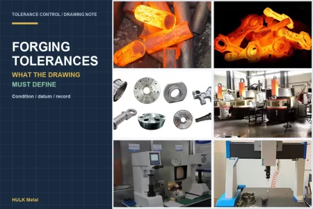
Dimensions are checked against the current drawing, datum scheme and stated process state. CMM or gauge selection follows the feature, and the report distinguishes as-forged, treated and machined conditions rather than mixing them into one result.
Mechanical and Hardness Verification
Where hardness, tensile or other mechanical evidence is required, the sample is linked to the material heat and outsourced treatment record. The test location, method and acceptance basis come from the drawing rather than a generic value borrowed from another valve project.
Surface Inspection
The forged and finished surfaces are reviewed for scale pits, laps, cracks, deep marks and conditions that interfere with machining or the pressure boundary. Acceptance follows the drawing and approved inspection basis; cosmetic work is not used to hide an uncontrolled indication.
NDT and Finished Inspection
When the order requires UT, MT, PT or another method, the buyer defines the method, coverage and acceptance level. Finished inspection confirms the drawing revision, dimensions, required records, surface condition and identification before release.
Packaging Inspection
The final check connects quantity, labels, protection and documents to the released lot. Packing is planned to protect machined faces, connection interfaces and identification so the buyer can trace the receipt back to the approved sample and production records.
Forging Factory and Workshop Route for Valve Parts
The factory route connects material identity, induction heating, die forging, outsourced heat treatment, in-house inspection and packing. Each step preserves the lot identity needed for a valve-part first article and the next production decision.
Production Workshops
Manufacturing Equipment
Inspection Center
Warehouse
Packaging
Surface Treatment Center
Production Workshops
The production team starts from the approved drawing and order split, then records the material heat, die reference and forging lot before valve parts move forward. The workshop review checks that the die set, process sheet and current drawing revision agree before production begins. The released worksheet follows the part through revision, die and lot status.
Manufacturing Equipment
The valve-part route uses induction heating with multiple forging presses and follows the approved die sequence. Part shape, section distribution and drawing requirements guide the selection; equipment tonnage is not published. Any change to billet allocation, blocker position or finishing sequence is reviewed before the first production lot. The chosen route must leave the required forged stock.
Inspection Center
In-house inspection covers material, dimensional, hardness and tensile checks according to the drawing. CMM and gauge selection follow the datum scheme and process state, while required NDT is connected to the buyer's approved method, coverage and acceptance basis. Inspection reports identify the sample, lot and drawing revision behind each result. Any missing or contradictory record is held before the disposition can close.
Warehouse
Incoming material and completed valve parts are stored with an order and lot identity. Storage protects machined faces, connection interfaces and marking from damage, while keeping incoming heats separate from parts already released to production. Material transfer does not break the link between heat identity, forging lot and release documents. Receiving and dispatch checks confirm that the part identity remains legible.
Packaging
Packing follows the agreed quantity, protection and destination. Labels, documents and packed quantity are checked against the released lot so the buyer can trace the receipt back to the approved drawing, treatment record and inspection result. Packaging protects critical faces and preserves the marking needed after shipment. The packed configuration is checked before the release documents are closed.
Surface Treatment Center
Cleaning, descaling and other finishing choices come from the valve drawing and purchase requirement. The approved operation is reviewed before it alters a specified face, and its record stays with the same production lot. Surface work does not replace dimensional, material or treatment evidence. The final surface condition is compared with the order before packing.
Why Work with HULK Metal on Forged Valve Parts
The working value is one OEM route from drawing review to first-article release, with explicit limits around pressure data, material, outsourced treatment, NDT and commercial terms. It keeps the technical and purchasing decisions tied to the same released scope.
One Stop Purchase
Drawing review, material sourcing, forging, machining where required, outsourced treatment, inspection and packing are coordinated through one HULK Metal contact. The buyer avoids rebuilding the handoffs between a forged body, an external treatment step and the document package. One production reference follows the part through acceptance, packing and dispatch, keeping engineering and purchasing on the same reviewed technical and commercial scope.
Get Higher Quality
Quality begins with drawing revision and material identity, continues through induction heating and die forging, and closes with inspection against the approved plan. ISO 9001, in-house dimensional checks and defined batch records support release without adding unsupported certificates. Treatment and NDT evidence are tied to the same sample and order basis. The release decision remains traceable from material heat to final disposition.
Get Faster
A complete drawing packet lets tooling, treatment and inspection questions surface earlier. Clear pressure-boundary features, material condition, machining boundaries and acceptance requirements reduce repeated technical clarification. Production timing still depends on drawing readiness, tooling, quantity and order conditions rather than a generic published lead time. A complete RFQ shortens the review loop before tooling starts and reduces avoidable stops after the first sample.
Save More Money
The total route is reviewed as material, forging, machining, treatment, inspection and packing. Fixing die and drawing decisions before tooling reduces hidden rework from unstated stock, mismatched datums or an inspection method that was never planned. That makes quotations comparable beyond the lowest untested starting price and lowers the chance of recovery work after the first sample. A clear scope also prevents unpaid secondary operations from appearing later.
Save More Time and Energy
One release chain connects drawing, material heat, forging lot, outsourced treatment and inspection results. The buyer spends less time reconciling disconnected documents and can focus on pressure-boundary fit, first-article disposition and the next production decision. Missing evidence becomes a defined hold instead of an informal promise. The buyer sees one decision path from technical review to packing and knows which input still blocks the next step.
Related Forging Guides for Valve-Part Buyers
These guides support the technical review behind a forged valve-part RFQ. The drawing article separates forged and machined requirements; the oil-and-gas scope article explains pressure-boundary ownership; the defect and tolerance articles show what to inspect; and the first-article guide closes the release chain without inventing acceptance values. Use them to prepare one consistent drawing, inspection and commercial package.