


Define the forged blank before the tool. Separate die-formed and machined features, place the parting line deliberately, name the material and outsourced treatment route, and connect first-article inspection to buyer-defined acceptance criteria.

Release the forged blank, die features and first-article evidence
Hand Tool Forgings: A Drawing-First Guide for OEM Buyers
-
Home>
-
Blog>
-
Technology>
Hand Tool Forgings: A Drawing-First Guide for OEM Buyers
18
2026.11
Hand tool forgings are quoted from a released forged blank, not from a finished-tool outline alone. The blank drawing must show which wrench, plier, clamp or hardware features are formed in the die, which surfaces remain machined, where the parting line may sit, how flash is controlled, and what evidence will release the first article.
This page is a drawing release guide for OEM buyers. It does not promise a catalogue of standard sizes, and it does not turn an unfinished CAD surface into a manufacturing instruction. The useful question is narrower: can a supplier compare one forged route with another and prove that the chosen route meets the drawing?

What Makes a Hand Tool Forging Different from a Machined or Fabricated Tool?
A hand tool forging starts with a hot metal preform that is shaped in closed dies under compressive force. Wrenches, pliers, pry bars, clamps, hammer heads, axe heads and other hardware forgings can share that broad process family, but their finished geometry is not the same as the forging geometry. Functional jaws, holes, gripping teeth, flats, threads and decorative surfaces may be formed, trimmed, machined, ground or heat treated in different sequences.
That sequence matters because a casting drawing, a bar-stock machining drawing and a billet-machined drawing can all describe the same finished outline while putting completely different demands on the forge shop. A forging quotation therefore needs a model of what leaves the press, a model of what leaves machining, and a statement of which acceptance features belong to each stage.
Table 1. Three release states that should not be combined in one undimensioned outline.
| Release state | What the buyer defines | Why the next supplier needs it |
|---|---|---|
| Finished tool | Final function, fit and appearance | Sets the buyer's acceptance target |
| Forged blank | Die-formed shape, draft, parting plane and flash | Sets die, press and trim scope |
| Machined part | Datum scheme, stock removal and final dimensions | Prevents hidden machining from being quoted twice or omitted |
Release test: if two suppliers can read the same drawing and disagree about what is forged, what is machined, or what is inspected, the drawing is not yet a comparable quotation package.
What the forged-blank drawing should control
The blank drawing should be a manufacturing document with its own revision and orientation. It does not need to expose every die detail, but it must control the information that changes the quotation and the acceptance decision.
✓ Show the forged envelope, the trim outline and the machining stock as a distinct state from the finished tool.
✓ Identify the datum scheme and the surfaces from which the blank and finished part are measured.
→ State left/right handedness, family size and revision so a similar tool cannot be quoted against the wrong cavity.
→ Mark the flash-line zone, trim direction, minimum fillet expectations and any surface where trim marks are unacceptable.
• Tie material, heat-treatment condition and inspection callouts to the same revision so the first article cannot mix documents.
• Record the sample quantity and whether the approved sample becomes the production reference.
A useful blank drawing also records the assumptions that were checked during review. If the finished part removes material from the jaw, pivot or striking end, the blank should make that removal visible instead of relying on a generic machining note. If a feature is left as-forged, its visual and dimensional acceptance should be stated. Those notes prevent a supplier from pricing a near-net forging while the buyer expects a fully machined tool.
The same discipline supports later change control. A revision to the grip profile may affect draft, trim access and weight distribution even when the finished tool's maximum length is unchanged. A revision to the jaw opening may change machining stock without changing the die outline. Keeping the forged and finished states in one revision history makes those consequences visible before a die is cut or a sample is approved.
Release-file check: one revision should contain the finished tool, the forged blank and the machining split. Do not let a drawing title imply all three.
HULK Metal reviews custom hand-tool and hardware parts as OEM forgings to the buyer's drawing. There is no standard tool catalogue and no stock-size shortcut behind the quote. The drawing remains the controlling document, while the final material grade, feasibility, dimensions, inspection and commercial terms are confirmed for that drawing and order.
Which Tool Features Should Be Formed in the Die?
The first decision is not “forge everything” or “machine everything.” It is a feature allocation. A forged shape earns its place where the load path needs continuous grain flow or where removing the same volume from solid bar would waste material and machining time. Machining earns its place where the final function depends on a datum, a closely held interface, a cut thread or a surface that cannot be produced reliably by the die alone.
The finished-tool outline rarely answers that question. A forged wrench may need generous transitions between handle and head; pliers may need material distributed around the pivot and jaw; a clamp may need a stable load path around an opening; and a hammer or axe may need a striking or cutting end that is later machined or heat treated. None of those decisions can be made safely from a silhouette alone.
Focus: head-to-handle transitions, jaw or opening geometry, bending load path, flash-line placement and the stock left for the final opening or interface.
Focus: pivot mass, jaw length, handle section, left/right identity, trimming access and whether the pivot is formed, drilled or finish-machined.
Focus: continuous load path around holes and bends, mounting interfaces, draft direction, marking area and the surfaces that must remain free of flash or trim marks.
Forged
Keep the main load path, broad transitions and sound bosses in the die-formed shape.
Machined
Reserve stock for jaws, holes, threads, grip surfaces and every datum-sensitive interface.
Verified
Tie dimensions, surface condition and marking to the same released revision.
The allocation should also record material removal. Forging commonly requires further machining to reach the finished part, so the blank must leave enough stock for the chosen process without hiding a second finished-tool design inside the forging. The exact allowance belongs on the drawing and is not filled by a website default.
How Do Load Path, Grain Flow and Dieability Shape the Blank?
A hand tool is a load-bearing object before it is a shape. A wrench transmits torque through the head and handle; pliers transfer force through jaws, pivot and handles; a clamp carries a closing load around its body; striking tools carry impact into a region that may later be machined or heat treated. The forging layout should distribute material along those paths rather than create sudden islands of mass connected by thin sections.
Section balance is part of the process, not only a CAD aesthetic. Very uneven sections change how metal fills the cavity and cool in the die. Long, thin projections and narrow ribs are harder to fill and more sensitive to die temperature and contact time. Generous fillets and radii are a practical way to reduce that difficulty, but they cannot rescue a design whose load path or die closure is fundamentally unclear.
01 Geometry
Show the forged blank, not only the finished tool. Mark the surfaces expected from the die.
02 Load
State where the tool bends, pulls, clamps or takes impact, and which direction governs the design.
03 Finish
Separate as-forged, machined, ground and surface-treated zones before quotation.
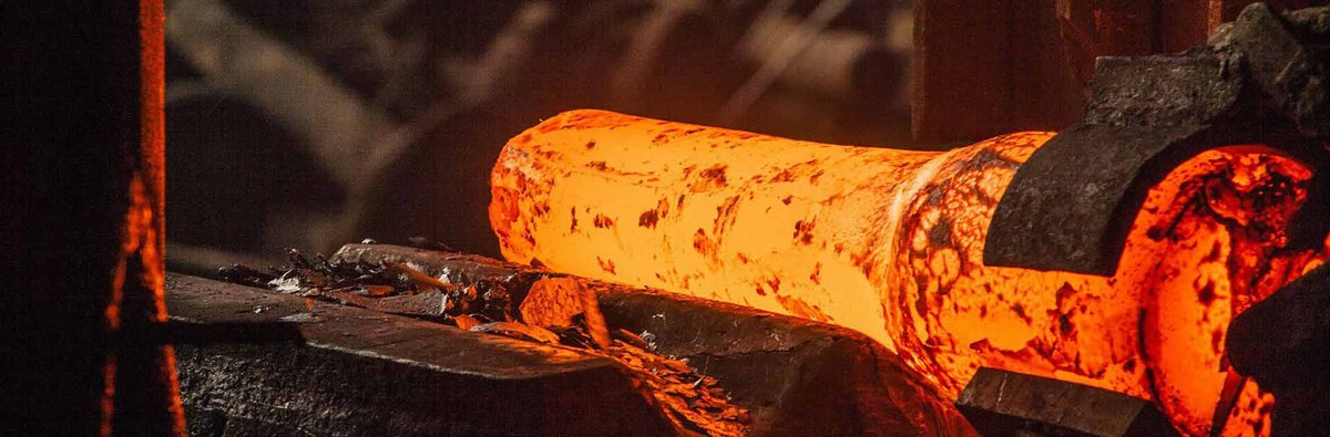
General steel impression-die design guidance commonly gives 5° to 7° draft for steel forgings and favors generous fillets and radii. Those are useful design-check figures, not a promise that every hand tool will use that angle or that HULK Metal has accepted the drawing. The governing draft, radii, blend and section change remain per drawing because the tool's parting plane, material and machining plan can change the route.
Grain flow is another reason not to treat the forging as a rough version of a machined outline. Deformation can orient the material structure through bends and transitions rather than cutting through it later. The benefit still depends on how the finished surfaces are machined. A deep cut through the load path can remove the very material continuity the forged blank was meant to preserve.
Dieability rule: when the finished load path cuts through the proposed grain direction or needs machining stock from a thin section, the blank geometry must be revised before tooling is priced.
At HULK Metal, the starting review compares the finished tool, the proposed blank and the machining split before discussing tooling. If those three views are missing or contradict one another, a useful feasibility answer cannot be separated from a guess about part geometry.
Where Should the Parting Plane and Flash Line Sit?
The parting plane decides where the die halves meet. The flash line is the visible result of metal escaping into the flash land before the flash is removed. Design guidance favors a single flat parting plane where possible and a parting surface through the centre of the forging rather than near an upper or lower edge. On hand tools, that choice affects draft direction, trim access, appearance and the dimensions that cross the plane.
Plane rule: the cleanest appearance is not automatically the best parting location. A plane that crosses a load path or traps trim access can create more rejection risk than a visible line placed on a non-functional surface.
Do not hide the parting decision in a note such as “match sample.” State the allowed plane, the flash-line zone and the result on surfaces that must remain visually or functionally clean.
Flash is not ordinary waste with no process role. Excess metal is squeezed out of the die, cools more rapidly and helps restrict further flow, which helps fill the cavity before the flash is removed. A drawing that treats flash as a cosmetic leftover misses the reason its thickness and land design matter. The trim operation also needs access, support and a defined edge condition.
Trim check: define how the flash is supported during removal and what edge or witness mark is acceptable after trimming.
Table 2. Parting-line decisions and the release consequence.
| Decision | Use when | Release evidence |
|---|---|---|
| Parting through the tool centre | A flat plane can preserve draft and symmetric material flow | Section view and marked plane |
| Contoured parting plane | The tool form forces the plane to follow a surface | 3D parting surface and trim drawing |
| Flash line outside a grip zone | Hand contact or appearance makes a central line unacceptable | Photograph or sketch of permitted zone |
| Cross-plane critical dimension | The functional tolerance must cross the die halves | Separate control of die closure and flash thickness |
Who owns the practical tolerance?
General impression-die references often quote different values across the parting plane and within one die half. The difference is not cosmetic. Dimensions across the plane are affected by die closure and are therefore tied to die wear and final flash thickness; dimensions fully contained within one die segment or half can be held more accurately.
A commonly reproduced industry table illustrates the point. For a 0.45 kg steel impression-die forging, it lists -0.15 mm and +0.46 mm rather than a symmetric plus-or-minus value. That is a general reference only. The HULK Metal value, datum and measured location still belong to the drawing and order, not to a generic website table.
Which Material and Heat-Treatment Route Should Be Named?
The material family should be named early because it changes the forging route, the surface condition and the heat-treatment question. HULK Metal reviews common carbon steel, alloy steel and stainless steel hand-tool forgings. The drawing should identify the material specification and the revision that governs acceptance; a trade name without a governing specification leaves the mechanical requirements open.
Carbon steel
State the governing material specification, required condition and any corrosion-protection route.
Alloy steel
Define the grade or specification, heat-treatment requirement and the locations where properties are verified.
Stainless steel
State the stainless family and finish; do not use magnetic-particle inspection as an assumed universal check.
Heat treatment is carried out by an audited partner and is not presented as in-house processing. The drawing and purchase order should therefore identify the required condition, the records the buyer expects and the verification method. Hardness bands, case depths and sampling positions are not website defaults; they must be confirmed per drawing.
Surface treatment belongs in the same release file. Plating, coating, blasting, polishing or other finishes can change dimensions, grip, appearance and inspection sequencing. If the buyer expects a finish after machining, state whether threads, holes or functional interfaces require masking. If the finish is only cosmetic, say so explicitly so it is not mistaken for corrosion validation.
Treatment control: the audited heat-treatment route is outside HULK Metal's own departments, so the purchase order must name the required records and property checks instead of assuming they travel with the material grade.
The final grade and treatment route remain per drawing. A statement that a hand tool is “forged from carbon steel” is not enough to compare quotations when one supplier assumes a different material specification, an as-forged surface and a different property test.
How Should Inspection Match the Failure Location?
Inspection starts with the failure location, not with a familiar acronym. A surface-open crack, seam or lap cannot be found by a method that only looks inside the section, while an internal discontinuity cannot be released by a surface-only test. The drawing should say what feature is being verified, where it is examined and which acceptance level applies.
For hand tools, the critical inspection locations usually follow the working path: jaw-to-pivot transitions, wrench head-to-handle blends, clamp corners, striking ends and machined interfaces. Those locations should be identified on the drawing rather than left to a general “inspect visually” note. First-article inspection then becomes a record of the released drawing, not a separate negotiation after the sample arrives.
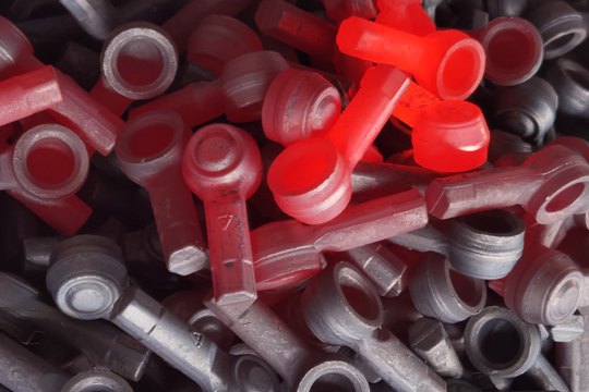
Table 3. Inspection method selected by the defect location and material condition.
| Evidence need | Usable method | Boundary |
|---|---|---|
| Surface-opening crack, seam or lap | Penetrant testing (PT) | Does not find a closed internal flaw |
| Surface or near-surface indication in steel | Magnetic-particle testing (MT) | Only ferromagnetic materials |
| Internal flaw or section condition | Ultrasonic testing (UT) | Only when the inquiry or order requires it |
| Dimensions and datum relationships | Dimensional inspection | Measured locations and datum scheme must be released |
| Material and treatment | Document review plus specified tests | Test method, location and frequency per drawing |
Acceptance criteria remain the buyer's responsibility. Published NDT practices can describe how to perform an examination, but they do not automatically supply a pass-or-fail level for that hand tool. If the purchase order leaves the level undefined, the first article may be technically inspected and still not be formally accepted.
The first-article file should connect the physical sample to the released drawing with measurements, material evidence, heat-treatment records, surface condition, NDT results where required and a signed deviation list. Any unapproved deviation should be visible before the production batch is released. HULK Metal's ISO 9001 claim supports the quality system context; it does not replace the part-specific acceptance callouts.
What Makes an RFQ Package Complete for Hand Tool Forgings?
A useful hand-tool forging RFQ is a small release file. It should let two suppliers quote the same blank, the same machining split and the same evidence. The file does not need to be long, but it cannot leave the route open while asking for a fixed price.
- 01 Drawing revision: released 2D drawing, finished tool model and forged-blank model if available.
- 02 Material: material family or governing specification, with the revision that controls acceptance.
- 03 Load path: bending, pulling, clamping or impact direction and the critical transitions.
- 04 Feature split: as-forged, machined, ground and surface-treated zones, plus the datum scheme.
- 05 Treatment: heat-treatment condition, outsourced-processing records and surface finish.
- 06 Inspection: dimensional program, NDT method, sample extent and buyer-defined acceptance level.
- 07 Commercial: annual volume, batch size, sample quantity, packaging and delivery destination.
In our RFQ review, the blank, finished part and drawing revision are read as one package. If the machining responsibility, parting plane or acceptance evidence is missing, the safe answer is to return the file for clarification before tooling work begins. That is faster than discovering an unresolved boundary after the sample is made.
Table 4. Route assumptions that make otherwise similar quotations incomparable.
| Hidden assumption | What changes | Close it with |
|---|---|---|
| “Quoted as forged” | No finish machining or only a trim operation | Blank drawing and surface list |
| “Quoted finish machined” | Machining stock, datums and cycle time | Machining responsibility matrix |
| “Quoted heat treated” | Treatment route, batch and records | Treatment callout and approved record list |
| “Quoted inspected” | Sampling, NDT and first-article scope | Inspection plan with acceptance level |
Tooling amortization is another common hidden assumption. A die with a different cavity sequence, trim arrangement or finishing operation is not the same commercial route even when the finished outline is identical. The buyer does not need to predict every internal cost, but the RFQ should state the volume, batch pattern and whether the sample is expected to become a production reference.
The same logic applies to tolerances, hardness, MOQ, tooling cost and lead time. They are not missing marketing details to be filled with a plausible number; they are order-specific conditions to be confirmed by drawing and commercial review.
Frequently Asked Questions About Hand Tool Forgings
Are hand tool forgings always finish-machined?
No blanket answer is safe. Forging commonly needs further machining to reach the finished component, but a tool drawing can leave some non-functional surfaces as-forged while reserving stock for jaws, holes, pivots, threads, datums and grip interfaces. The buyer should state which surfaces remain as-forged, what allowance is left, where the datum scheme starts and how both the blank and finished part are inspected. Without that split, one supplier may price a near-net blank while another prices a fully machined tool.
Can you quote from a finished 3D model only?
Not reliably. Add the forged-blank view and drawing notes.
Do you make lifting hooks?
No. Lifting hooks are outside this page and outside the current non-core line. The page's hand-tool scope covers OEM wrench, plier, clamp and related hardware forgings only.
Which certificate and heat-treatment statements apply?
ISO 9001 is the only certificate claim used on this site. Heat treatment is carried out by an audited partner, not in-house. The drawing must still state the required treatment condition, records, test method and sampling basis. Neither the quality-system claim nor the outsourced route replaces the buyer's part-specific acceptance criteria.
Release the Drawing Before You Release the Tool
A hand tool forging is easier to quote when the buyer stops treating the finished tool as a single manufacturing instruction. Separate the forged blank from the machined part, show the load path, place the parting plane deliberately, name the material and treatment, and state how the first article will be accepted. Those decisions are the information base shared by the forge shop, machining supplier and quality team.
HULK Metal reviews hand-tool and hardware forgings as OEM parts to the buyer's drawing. Carbon steel, alloy steel and stainless steel routes can be evaluated; gears, shafts, aluminium, cold forging, ring rolling, forged wheels and titanium remain outside the scope, and lifting hooks are not part of this page.
Next review: compare the released drawing, blank model and sample plan before asking for a tooling commitment.
For a useful first response, send the released 2D drawing, finished and blank models if available, material specification, critical load path, machining split, treatment callout, NDT requirement, volume and sample plan. We will confirm feasibility and all drawing-specific values for that package.
Images on this page show representative hot die forging and inspection scenes from HULK Metal's own site assets. They are process illustrations, not customer parts, part numbers or production references.
Article Navigation
Others You Might Want to Know
Article Navigation
Industries
Foundries
More Forging Drawing and Release Guides from HULK Metal

Previous article: None
Next article: ACSR Conductor Gripper Sizing: Six Checks Before You Release the Drawing