


A drawing-controlled guide to conductor OD, jaw contact, pull path, eye fit, release direction and inspection evidence.

Conductor OD, jaw contact, pull path and inspection evidence
ACSR Conductor Gripper Sizing: Six Checks Before You Release the Drawing
-
Home>
-
Blog>
-
Technology>
ACSR Conductor Gripper Sizing: Six Checks Before You Release the Drawing
16
2026.11
ACSR conductor gripper sizing starts with the conductor, not a catalogue model. Record the conductor construction, exact outside diameter, jaw-contact window, maximum line-pull condition, eye interface and inspection requirement before you ask for a quotation.
A nominal AWG, kcmil, MCM or utility cable code is a useful identifier. It does not, on its own, release a production drawing. The same nominal conductor can differ in strand combination, surface condition and actual outside diameter. The pulling equipment adds another set of interfaces: eye, pin, latch, hoist or come-along.
Use this rule for the whole page: the final grip rating, dimensions, material, hardness, heat-treatment requirement and acceptance level must come from the approved drawing and order. This article explains how to prepare and verify that release; it does not replace the purchaser's engineered pulling method.
What “Correctly Sized” Means for an ACSR Conductor Gripper
A correctly sized ACSR conductor gripper seats around the conductor, carries the pull through the body and eye, opens and closes in the direction your crew can control, and can be inspected against a defined record. Those are connected decisions. Changing one input can move the jaw, body, pin or attachment geometry.
The six checks below form the Fit Stack. Work from conductor to attachment, then turn the result into a drawing and purchase-order packet. Do not begin with the largest model that looks close.
The conductor-gripper fit stack
Conductor: identify the conductor family, stranding or cable code, actual outside diameter and surface condition. This defines the envelope the jaws must accept.
Jaw: check contact shape, usable length, opening, seating pattern and the acceptable conductor deformation limit. The jaw is where grip and damage are traded against each other.
Body and pivot: confirm the body, pin and linkage arrangement that carry the pull from the jaws to the eye. A correct jaw opening cannot rescue a weak or misaligned load path.
Eye: match the eye opening and thickness to the puller, come-along, hook or adapter. The connection should sit without side loading, pinching or a loose pin.
Release: define where the latch or release sits, what keeps the conductor from leaving the jaws, and how the crew can inspect and operate it with gloves or standard tools.
Six inputs that turn a conductor description into a reviewable grip requirement.
| Input | Record | Why it changes the grip |
|---|---|---|
| Conductor family | ACSR, ACSS, AAC, copper or covered cable | Changes jaw material, contact pattern and surface protection |
| Exact envelope | Outside diameter and strand combination | Controls opening, seating and jaw travel |
| Pull condition | Maximum pull and work-method limits | Drives body, pin and eye strength requirements |
| Puller interface | Eye sketch, pin or hook arrangement | Prevents a correct grip from being unusable on site |
| Release method | Latch, trigger or open direction | Sets safe placement and controlled removal |
| Evidence | Material, finish, records and acceptance level | Turns the sample fit into a repeatable order |
Send the conductor schedule and pulling method before asking for a model. A quotation built only on “ACSR 240” or “ACSR 500” is a starting point, not a controlled grip specification.
Start with the Conductor, Not the Grip Model
The first question is not “which grip fits a 240 or 500?” It is “what conductor envelope has to be gripped, and on which surface?” Conductor type and construction belong in the same breath as outside diameter.
Bare ACSR exposes aluminium strands around a steel core. ACSS, AAC, copper and covered cables present different outer surfaces. A jaw that bites effectively on one may mark, crush or slide on another. That is why manufacturer guidance begins with the conductor type and actual diameter rather than a single nominal size.
Use at least two identifiers
A. Record the conductor family and construction.
B. Record the manufacturer code or circular mils with strand combination.
C. Confirm the actual outside diameter from the current conductor data or a measured sample.
D. State whether the gripped surface is bare, greased, aged, covered or otherwise changed by service.
A distributor specification for large-diameter Chicago-style grips makes this explicit: orders should specify exact outside diameter, circular mils with strand combination, or the manufacturer's cable code. Those identifiers overlap, but they do different jobs. The code connects the order to the conductor record; the OD defines the physical space the jaws must wrap.
Release rule
If the only available identifier is a nominal conductor size, keep the job at quotation-review stage. Do not release production until the actual conductor record and diameter basis are agreed.
This is also where many comparisons are framed on the wrong basis. One supplier may label a grip by a nominal conductor range, another by maximum opening, and a third by rated load. Those columns are not interchangeable. The buyer must place all three back onto the same conductor envelope before drawing conclusions.
A measured OD note prevents a price based on the wrong envelope. It also tells the supplier whether two adjacent nominal conductors can share one jaw pocket or should remain separate tools.
Measure the Interface: OD, Strand Pattern and Surface
Measure the conductor where the jaws will actually sit. The nominal conductor table is useful for identification; the interface measurement is what the jaw must accept.
Record the diameter basis. Is the value taken from the conductor manufacturer's current table, measured on a new sample, measured after installation, or calculated from a nominal code? Those are different evidence levels. Put the basis beside the number so the quotation reviewer does not assume the tightest or loosest case.
For a new or field-aged conductor sample, take readings around the circumference and along the length that will sit inside the jaws. If the envelope varies across the production batch, quote the range rather than one convenient reading. Do not hide a mixed-stock condition inside a single nominal conductor name.
A conductor-envelope record that can be checked by both buyer and supplier.
| Field | Good record | Weak record |
|---|---|---|
| Diameter | Value, unit, source and measurement basis | “Standard 240” with no diameter |
| Construction | Strand combination or manufacturer code | Family name only |
| Surface | Bare, covered, greased or service-aged | Unstated condition |
| Variation | Expected diameter range across the order | One nominal value for mixed stock |
Inspect the sample before tooling
For a new custom grip, ask for a sample fit against the agreed conductor envelope. Observe whether the conductor seats across the intended jaw length. Check that the nose, latch or body does not touch an incompatible surface before the jaws close. If the conductor is covered, the review should also identify where the covering may compress.
The sample should not be judged only by “it closes.” Closure is a mechanical event; seating is the engineering condition. Photograph the seated conductor from the jaw ends and from the side, then keep the images with the approval record. That record becomes the visual reference for later batches.
A measured OD and a sample photo keep the quotation on the correct envelope. Send both when the conductor is brought in from more than one source.
Match Jaw Geometry to Contact and Deformation Limits
Jaw geometry decides whether the grip holds through contact or damages the conductor to create holding force. The desired balance is set by the conductor, the pull condition and the acceptance rule.
Southwire's ACSR installation guidance is direct on one point: grip jaws may be round or oval, but not V-shaped. The reason is contact distribution. A round or oval cradle spreads load around more of the conductor surface. A V-shape concentrates contact at two lines and can cause local deformation while leaving other areas unseated.
Jaw length affects more than the model-table value
Longer jaws can distribute contact over more conductor length, but they also affect tool weight, handling, nose clearance and the distance between the conductor and the puller. A short jaw may suit a compact tool, yet it can place more of the grip demand on a small contact patch.
Stop 01: Selecting jaw length solely from a competitor's model column.
Avoid 02: Allowing a serrated profile to mark a surface the buyer considers unacceptable.
Never treat: A comfortable jaw opening as proof of correct seating.
Approve only: A trial fit with a photo and dimensional record.
Ask for the jaw decision in writing
The drawing should show the jaw form, opening, contact length and any surface requirement. If the buyer has a deformation limit, it should be stated as an acceptance condition, not inferred from a finish callout. If the conductor is covered, define whether the jaw contacts the covering or a stripped section.
Round or oval contact
Use when the conductor needs a broad cradle and controlled deformation. Confirm the actual envelope before choosing the opening.
Surface protection
Covered or finish-sensitive conductors need the contact surface defined before the jaw profile is approved.
V-shaped contact
Reject for bare ACSR installation when the work is governed by the round-or-oval rule; verify the purchaser's specification.
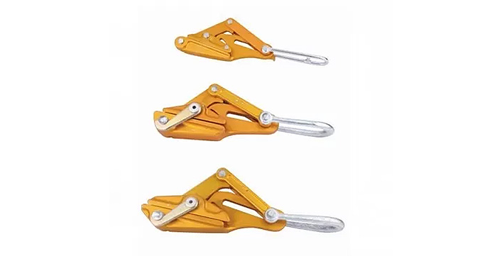
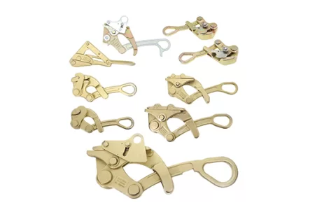
Include this jaw sketch in the RFQ. It gives the supplier a concrete geometry to quote and gives the inspector a visible feature to compare with the approved sample.
Treat Load, Puller and Eye as One Chain
A grip is one link in a pulling chain. The conductor, jaw, body, pivot, eye, pin, latch, connector and puller all have to work in the same direction.
The final working-load rating belongs on the approved drawing and order. This page deliberately avoids quoting one universal rating because model, material, geometry, test basis and application conditions can change the release. The buyer should instead specify the maximum pull condition and the record that proves the selected design is suitable.
-
Working pull: state the routine maximum the line crew expects during the approved operation.
-
Proof or test pull: state whether a separate test condition exists and which record proves it.
-
Hardware limit: identify the puller, hook, swivel or adapter limit connected to the grip eye.
Figure 1. The grip decision follows one continuous load path from conductor contact to the pulling line.
Check the eye before the body is approved
A part can pass its material and jaw checks and still fail at the connection point. Measure or sketch the eye opening, thickness and pin interface. State whether the pulling line uses a hook, shackle, adapter, swivel or direct pin. If the puller pulls off-centre, the jaw contact pattern can change.
The eye is also a handling feature. A tight eye can be difficult to attach in gloves; an oversized eye can produce a loose pin and side load. Match the interface to the tools the crew will actually use, not only to the drawing note.
Separate the maximum working pull from any proof or test pull and from the hardware limit. If the RFQ supplies only one maximum value, the supplier should ask which condition it represents before selecting the body and eye. This prevents a test condition from being confused with routine service.
Send the puller eye or a dimensioned sketch. That single attachment step often explains why two grips with similar jaw openings behave differently on site.
Choose the Release Direction and Latch Around the Method
A conductor grip has to be placed, seated, pulled and released by a real crew. The latch and opening direction must fit that sequence.
Check which side of the tool is presented to the conductor, what keeps the conductor from leaving the jaw during the pull, and how the crew confirms full engagement. A latch that works on a bench may be hard to operate with gloves, from an awkward angle or beside another connector.
Mark: Show the intended pull direction on the drawing.
Specify: State whether the latch is required to be spring-loaded, manual or lock-open.
Photograph: Define the open and closed positions in a sample record.
Confirm: Check that the puller, hook or adapter does not touch the latch.
Add: Put the release check into the goods-in inspection record.
If the work method is controlled by a utility standard, the standard should be named in the RFQ and attached where permitted. The supplier can then review the grip geometry against the stated interface. The supplier should not invent a work method from a product photograph.
For an OEM drawing match, include the latch and release direction in the approval. A sample that only demonstrates jaw closure has not demonstrated the full operating sequence.
Stop a Bad Fit Before the Conductor Is Pulled
Most sizing errors announce themselves before the pull reaches working tension. The trick is to look at the contact patch, the eye and the release path as one system.
A grip can look closed while the conductor sits on the nose, sits too high in the jaw or is held by only a short section of jaw length. Inspect from both ends and from the side. Look for a full cradle, an aligned eye and a latch that is not being pushed by the connection hardware.
Fit symptoms and the evidence that should be checked before a pull.
| Symptom | Likely mismatch | Verification |
|---|---|---|
| Conductor rides on jaw nose | Opening or body clearance too small | Recheck OD and sample seating |
| Only a short jaw section contacts | Jaw length or geometry mismatch | Mark contact length on trial fit |
| Conductor slips during light pull | Surface, jaw form or seating problem | Stop; verify profile and surface |
| Visible flattening or marking | Contact pressure or profile mismatch | Compare to drawing and sample |
| Eye or pin binds under load | Puller interface mismatch | Check eye, pin and side clearance |
| Latch cannot release cleanly | Release direction or tool clearance | Operate in the intended work position |
Stop the trial when the evidence conflicts
If a trial fit shows both poor seating and conductor marking, changing only one feature may move the failure elsewhere. The drawing review should revisit the conductor envelope, jaw profile and load path together. Record the rejection with the conductor sample, the grip condition, the eye arrangement and a clear photo.
Mark these defects as rejection criteria in the order. “No visible damage” is not a controlled test unless the order states what surface and deformation condition is acceptable.
Build a Drawing and RFQ Pack That Removes Guesswork
The RFQ should give the supplier enough controlled information to quote the grip, not only enough information to find a similar catalogue image.
On our quotation review, the conductor description and the pulling interface are read together. A nameplate-style model selection can start the discussion, but a drawing release needs the actual conductor envelope, material, finish, attachment sketch and acceptance record.
RFQ packet for a drawing-controlled ACSR conductor gripper.
| Packet item | What to include | Decision it controls |
|---|---|---|
| Conductor record | Family, code, strand, OD and surface | Jaw opening and seating |
| Pull plan | Maximum pull and method limits | Body, pin and rating basis |
| Interface sketch | Eye, pin, hook or adapter dimensions | Attachment fit and side clearance |
| Material | Grade or property requirement | Forging and heat-treatment route |
| Finish | Coating or surface condition per drawing | Corrosion and conductor contact |
| Acceptance | Dimensions, records, trial fit and test method | Batch release and goods-in check |
| Commercial | Quantity, packing, documents and delivery | Order planning; values confirmed on request |
RFQ readiness check
Static checklist: all eight items remain visible without JavaScript.
- Conductor family and construction recorded
- Exact OD plus strand combination or cable code supplied
- Pull condition and maximum working demand stated
- Puller eye or connector sketch included
- Latch and release direction shown
- Material and heat-treatment requirements listed
- Finish and conductor-contact condition defined
- Inspection records and sample approval defined
Use the checklist as the RFQ cover sheet. If an item is missing, mark it as an open technical decision rather than allowing the supplier to replace it with an assumed model value.
Inspection Evidence at Sample, Batch and Goods-In
A sample fit is the first evidence gate. Batch records and goods-in checks show whether the approved fit remained stable in production.
HULK Metal produces cable and wire grips as OEM hot die forged parts, with in-house inspection. Heat treatment is completed by an audited external partner. The order should state which records the buyer expects for material, heat treatment, dimensions, visual condition and any functional pull test.
Three inspection gates
-
Gate 1: Sample fit
Seat the sample on the agreed conductor envelope. Record jaw contact, open and closed positions, eye fit, latch operation and conductor condition.
-
Gate 2: Batch release
Verify drawing dimensions, material and heat-treatment records, surface condition, pin and latch function, and the approved inspection method.
-
Gate 3: Goods-in
Match the delivered batch to the approved sample, check labels and records, and repeat the fit check with the conductor or a controlled replica.
Goods-in inspection should match the same control used at sample approval. If the sample was approved on a measured OD but the delivery is checked only against a nominal code, the acceptance chain has a gap.
Ask for the inspection record format before production. The buyer can then confirm that the record will capture the dimensions and functions that matter, instead of receiving a certificate that repeats the model name only.
FAQ: ACSR Conductor Gripper Sizing
Does the MCM or conductor code alone tell me the exact grip size?
No. It identifies the family, while the jaw needs the actual envelope. Write the code beside the conductor data or a measured sample. Mixed stock needs the full range.
Should an ACSR grip have round, oval or serrated jaws?
Start with the conductor and work-method requirements. Published ACSR installation guidance permits round or oval jaws and rejects V-shaped jaws. Serrations or other grip features also need approval against the acceptable conductor deformation and surface condition.
Can one grip cover both bare ACSR and covered cable?
Only if the approved drawing explicitly covers both surfaces and envelopes. Covered cable changes contact and deformation limits.
What is the one value I should ask the supplier to confirm?
There is no single safe number without the application basis. Ask for the approved drawing release: conductor envelope, jaw opening and contact, body and eye geometry, material, heat treatment, finish, working-load basis, inspection method and batch records. Ask the supplier to identify every value that remains conditional.
If the buyer supplies a conductor code but no actual OD, the review should not pretend that the envelope is known. If the puller sketch is missing, the eye decision remains open even when the jaw calculation looks complete. If the purchase order names a visual limit but does not define the inspection record, production may pass a condition the buyer intended to reject. For a quotation review, send the missing drawing or work-method input with the note that it controls the release. Contact us for details when a required input is unavailable.
Final rule: size the conductor envelope first, then the jaw, then the load path and release. A quick model match is useful only after those four decisions are written down.
For an OEM conductor-gripper review, send the conductor schedule, actual OD or cable code, pulling arrangement, eye sketch, material and finish requirements, and the inspection record you expect. HULK Metal can then match the forged part to the drawing instead of asking the production team to guess from a nominal conductor name.
Article Navigation
Others You Might Want to Know
Article Navigation
Foundries
More Conductor Grip Selection and Inspection Notes


Previous article: None
Next article: Oil & Gas Forged Parts: Upstream, Pipeline, or Refining?